CPLD
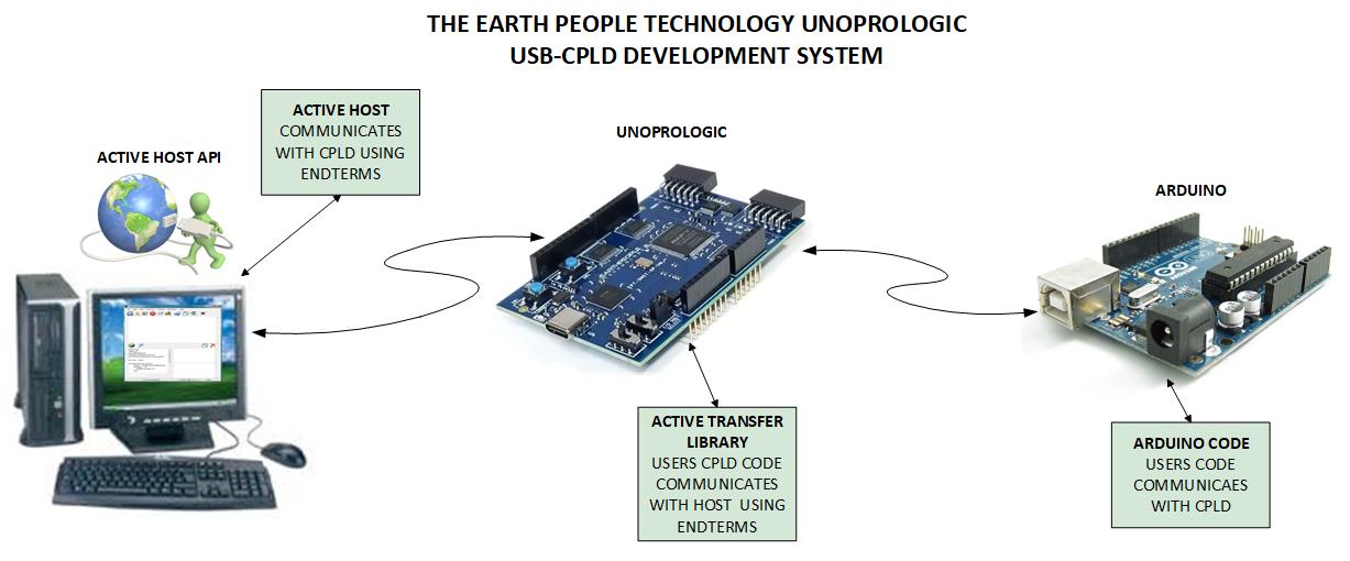
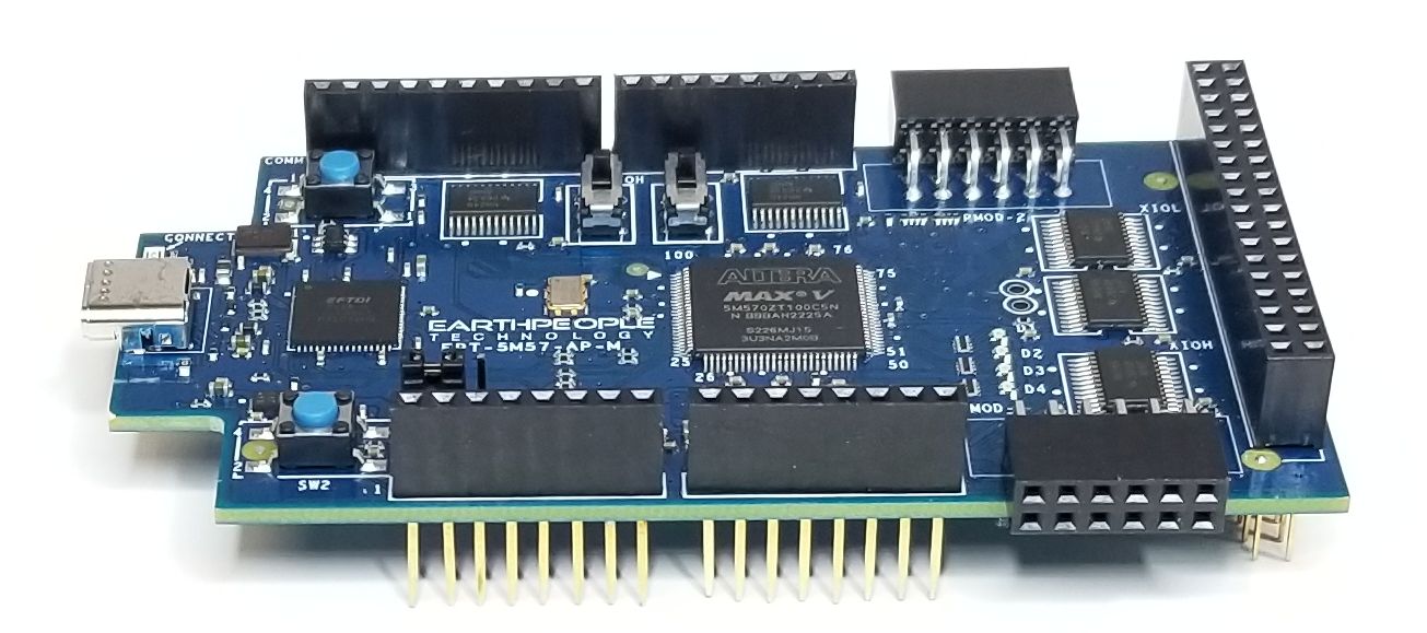
UnoProLogic USB-CPLD Development System

UNOPROLOGIC USB-CPLD
DEVELOPMENT
SYSTEM
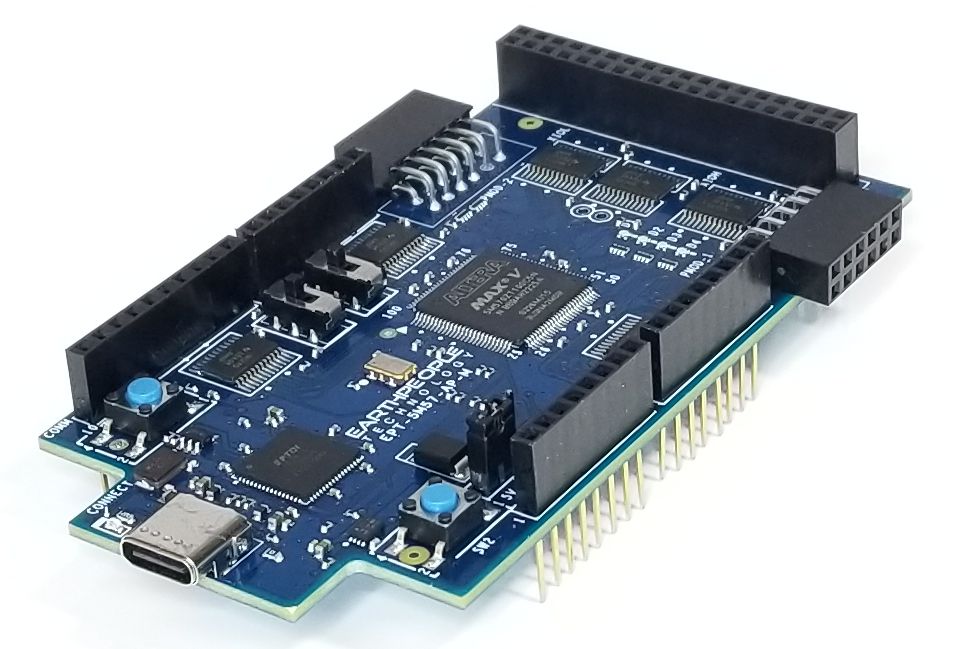
The UnoProLogic is an easy to use
CPLD development system. It includes
a four Channel ADC and built in
programmer
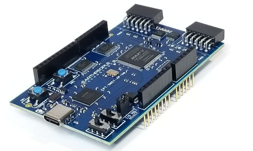
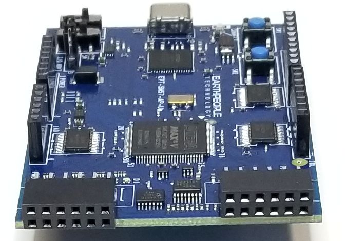
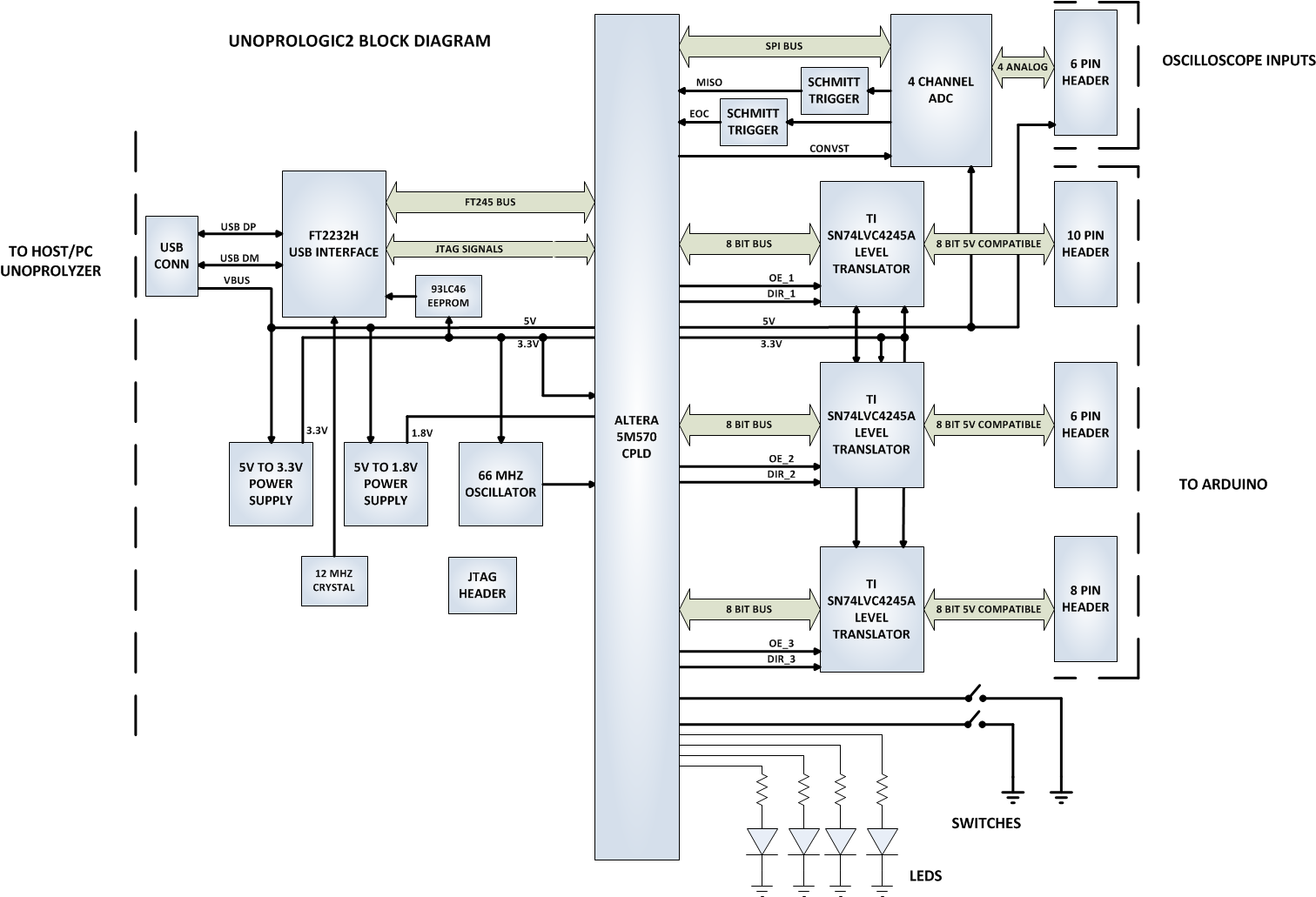
| The UnoProLogic makes programmable logic easy with an all inclusive development platform. It includes an Altera 5M570 CPLD, JTAG programmer, and a four channel ADC with 300KS/second sample rate. You can create your HDL code, program it into the CPLD and interact with the hardware via a Windows PC. |
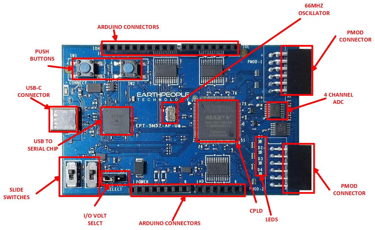
Hardware Features:
|
| The UnoProLogic DVD provides detailed step by step instructions to quickly guide the user to create a project. Once the Quartus software is on your desktop, we will show you how to create a project, write you first LED blinky code, compile and program the CPLD. |
|
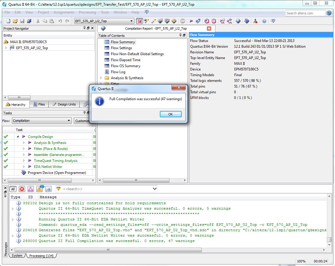
Programming the CPLD
| The CPLD on the UnoProLogic can be programmed with the code created by the user. Programming is quick and easy. All that is required is a standard USB-C cable and the Quartus Software installed on the PC. There are no extra parts to buy – just plug in the USB cable and connect the UnoProLogic to the PC |
![]()
![]()
Arduino Compatibility
| The UnoProLogic has four stackable headers that positioned to allow connection with the Arduino Uno. You can use the CPLD to perform high speed communications, multi sensor fusing or extra storage capacity. |
Connecting To Hobby Electronics Made Easy
| The UnoProLogic easily connects to other Hobby Electronics. The durable 74LVC82245 Bus Transceivers allow up to 50mA per Output on the Stackable Headers. This kind of power can drive all kinds of electronics such as long distance cables, LEDs, and high speed electronics. |

Programmable Logic Code Development
| It also provides a high speed data transfer mechanism between an Arduino board and a host PC. The EPT USB-CPLD development system provides a convenient, user-friendly work flow byconnecting seamlessly with Intel’s Quartus Prime Lite software. The user will develop the code in the Quartus environment on a Windows Personal Computer. The programmable logic code is loaded into the CPLD using only the Quartus Programmer tool and a standard USB cable. The Active Host SDK provides a highly configurable communications interface between Arduino and host. It connects tsransparently with the Active Transfer Library in the CPLD code. This Active Host/Active Transfer combination eliminates the complexity of designing a USB communication system. No scheduling USB transfers, USB driver interface or inf file changes are needed. The EPT USB-CPLD development systemis a unique combination of hardware and software. |
| Use the C# examples included in the DVD to create your own display Window on the PC.The user comes complete with tutorial to instruct the user to easily build a Windows program that can display any data from your Arduino or other electronic device. The C# interface uses similar function calls to the Arduino function calls. |
4 Channel Analog to Digital Converter
| Examine four analog channels running up to 300 KSamples/second. The hardware has been simplified to remove extra cost. The input signals are limited to 0 to +5Volts and the sample rate is shared across all four channels. If you run one channel only, it will take advantage of the 300KSamples/second. If you run four channels, each channel will have a maximum sample rate of 75 KSamples/second. |
The UnoProLyzer Application
| The UnoProLyzer is an Open Source Oscilloscope Application created by Earth People Technology. This application runs on a Windows PC. It sends commands to and receives the data from the UnoProLogic and stores each channel data in its own separate buffer in memory. The UnoProLyzer collects all samples from each channel by streaming across up to four dedicated communication “pipes”. The traditional USB oscilloscope performs all of its functions down at the hardware level. This includes |
|
| These scopes will then send the selected data to be displayed on a laptop. Effectively using the laptop as a dumb terminal. However, the modern laptop is extremely powerful with multi-core processors and multi-threaded operating systems. So, why not take advantage of the processing power on the laptop. This is what the UnoProLogic and UnoProLyzer do so well. The UnoProLogic commands the ADC to start a conversion on the channels selected by the user. It then waits for the ADC to complete the conversion on all channels. It transfers the data for each channel across its own dedicated communication pipe. Then starts the process over again. The UnoProLyzer application will accept each data word and decode the pipe number it came across. It stores each word into a separate buffer for each channel. The UnoProLyzer then performs post processing on each data word. It performs trigger detection, smoothing, sorting, scaling and searching. It then displays the data set in 500 data point segments. |
Programming Features:
|
Kit Contents
| UnoProLogic kit contains the UnoProLogic and a DVD which includes the User Manual that walks the user through setting up the drivers, software, how to use to the test application. There is also a full tutorial in writing your first CPLD project, C# application and Arduino code. All the code for the projects are included. |
Downloads
| 85-000010 | UnoProLogic USB/PLD Development System User Manual | UNO_USB_CPLD_DEV_SYS_UM.pdf |
| 95-000010 | UnoProLogic USB/PLD Development System Data Sheet | UNO_USB_CPLD_DEV_SYS_DS.pdf |
| 45-000010 | UnoProLogic USB-CPLD Development System Project DVD | UNO_USB_CPLD_PROJECT_DVD |
| 55-000010 | UnoProLogic USB-CPLD Development System Schematics | UNOPROLOGIC_SCHEMATICS.PDF |
| 35-000001 | EPT Drivers | CDM212364_Setup.ZIP |
MegaProLogic Development Board for Arduino 2560 Mega
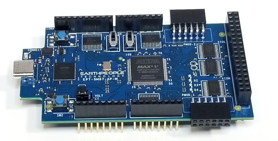
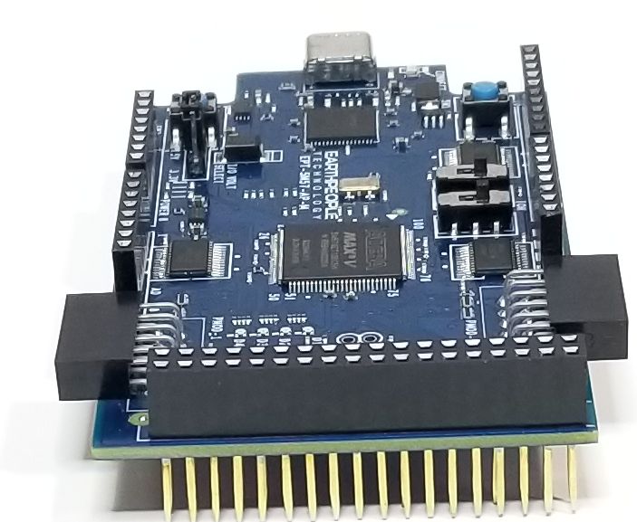
The MegaProLogic is an easy to use
CPLD development system.
Purchase at these webstores:
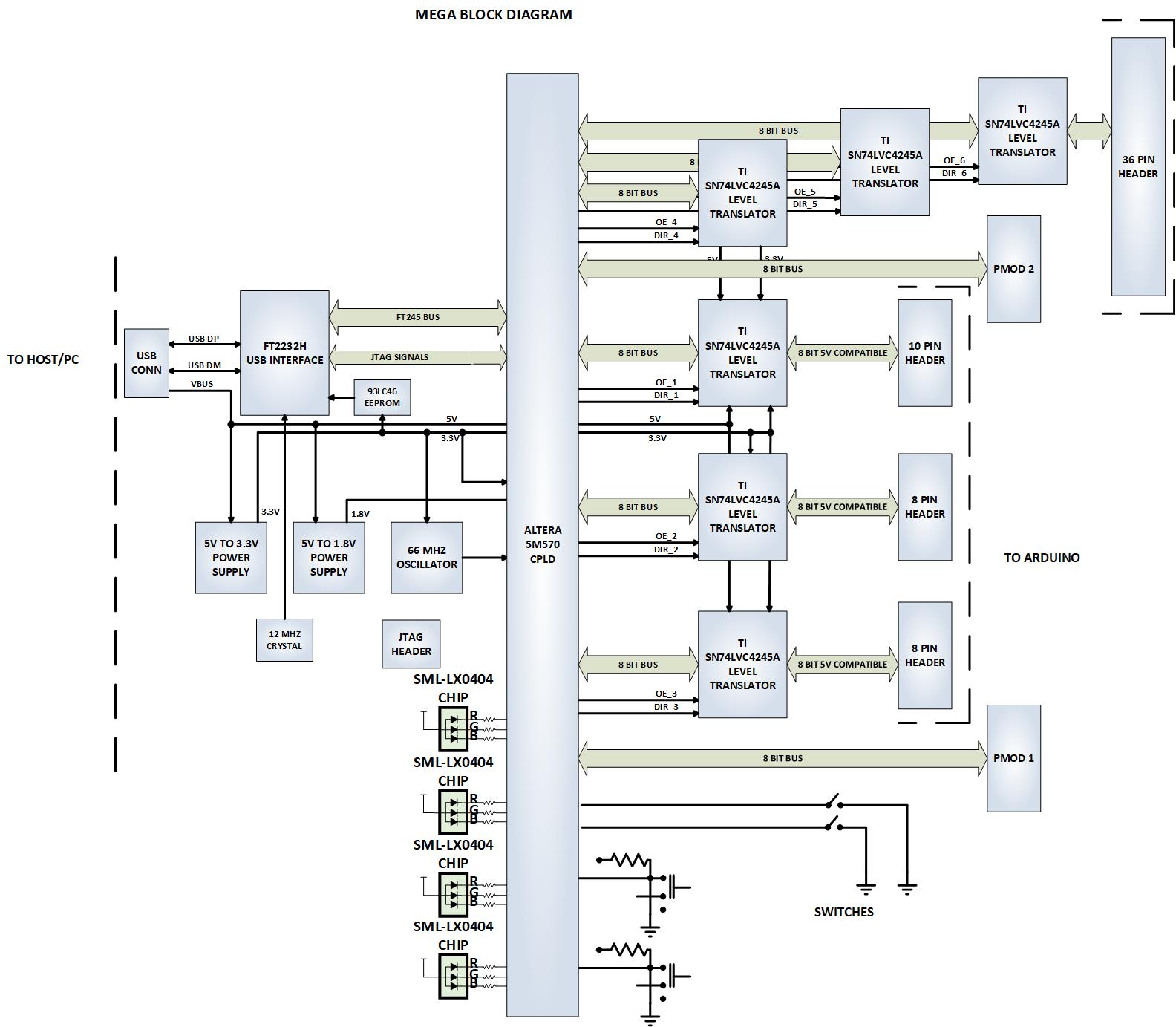
| The MegaProLogic makes programmable logic easy with an all inclusive development platform. It includes an Altera 5M570 CPLD, JTAG programmer, and a 32 General Purpose Inputs/Outputs. You can create your HDL code, program it into the CPLD and interact with the hardware via a Windows PC. |
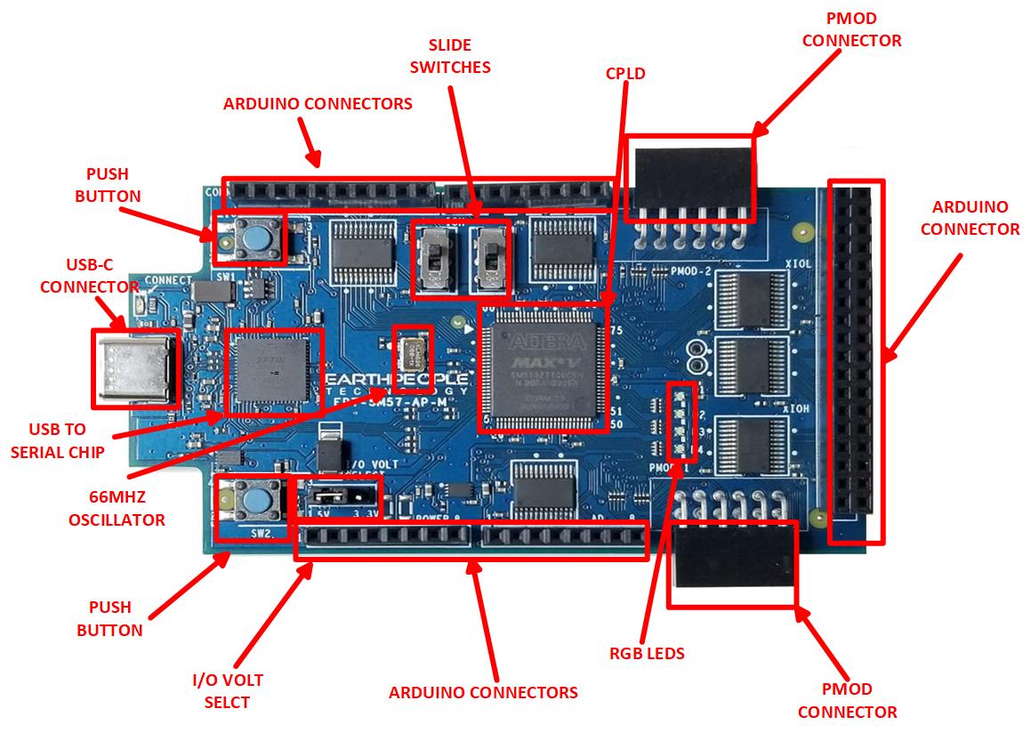
Hardware Features:
|
| The MegaProLogic DVD provides detailed step by step instructions to quickly guide the user to create a project. The entire Quartus Prime Lite software is included on the DVD. This let’s you bypass the lengthly download process involved in getting the 3.6 GB file. Once the Quartus software is on your desktop, we will show you how to create a project, write you first LED blinky code, compile and program the CPLD. |
|
Programming the CPLD
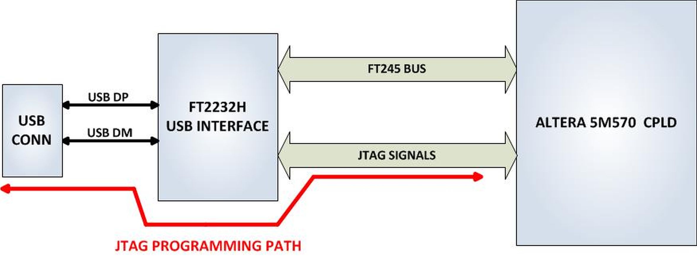
| The CPLD on the MegaProLogic can be programmed with the code created by the user. Programming is quick and easy. All that is required is a standard USB cable with a Micro B connector and the Quartus Software installed on the PC. There are no extra parts to buy – just plug in the USB cable and connect the MegaProLogic to the PC |
![]()
Connecting To Hobby Electronics Made Easy
| The MegaProLogic easily connects to other Hobby Electronics. The durable 74LVC82245 Bus Transceivers allow up to 50mA per Output on the Stackable Headers. This kind of power can drive all kinds of electronics such as long distance cables, LEDs, and high speed electronics. |
Programmable Logic Code Development
| It also provides a high speed data transfer mechanism between the MegaProLogic board and a host PC. The MegaProLogic development system provides a convenient, user-friendly work flow by connecting seamlessly with Altera’s Quartus Prime Lite software. The user will develop the code in the Quartus environment on a Windows Personal Computer. The programmable logic code is loaded into the CPLD using only the Quartus Programmer tool and a standard USB cable. The Active Host SDK provides a highly configurable communications interface between CPLD and host. It connects transparently with the Active Transfer Library in the CPLD code. This Active Host/Active Transfer combination eliminates the complexity of designing a USB communication system. No scheduling USB transfers, USB driver interface or inf file changes are needed. The MegaProLogic development systemis a unique combination of hardware and software. |
| Use the C# examples included in the DVD to create your own display Window on the PC.The user comes complete with tutorial to instruct the user to easily build a Windows program that can display any data from user code or other electronic device. The C# interface uses similar function calls to the Arduino function calls. |
Programming Features:
|
Kit Contents
| MegaProLogic kit contains the MegaProLogic and a DVD which includes the User Manual that walks the user through setting up the drivers, software, and the test application. There is also a full tutorial in writing your first CPLD project and C# application. All the code for the projects are included. |
Downloads
| 85-000040 | MegaProLogic CPLD Development System User Manual | MEGA_USB_CPLD_DEV_SYS_UM.pdf |
| 95-000040 | MegaProLogic CPLD Development System Data Sheet | MEGA_USB_CPLD_DEV_SYS_DS.pdf |
| 45-000040 | MegaProLogic CPLD Development System Project DVD | MEGAPROLOGIC_USB_CPLD_PROJECT_4.5_DVD |
| 55-000040 | MegaProLogic CPLD Development System Schematics | MEGAPROLOGIC_SCHEMATICS.PDF |
| 35-000001 | EPT Drivers | EPT_2.08.24.ZIP |
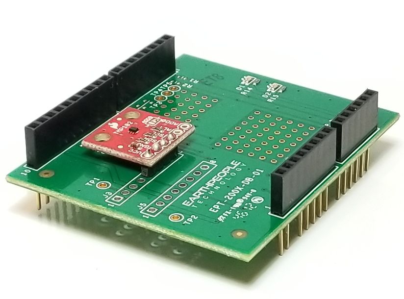
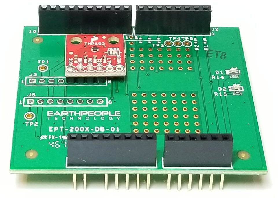
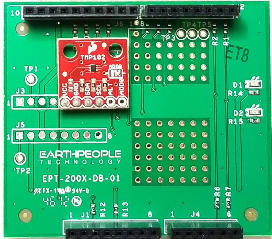
TMP102 Uno Docking Board
TMP102 TEMPERATURE SENSOR
DOCKING BOARD
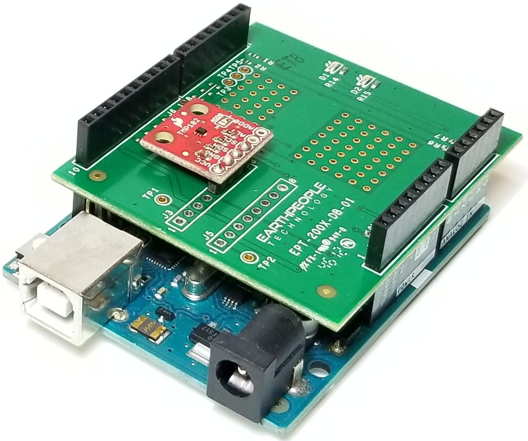
The TMP102 Temperature Sensor Docking Board
Quickly and easily connects the TMP102 to
the Arduino Uno platform
| The EPT-200TMP-TS-U2 is a temperature sensor mounted on a docking board. The board is designed to fit onto the Arduino Uno platform. It is compatible with the +5V Arduino’s and requires no external hook wires. Just plug the EPT-200TMP-TS-U2 into the Arduino and load the code. The TMP102 temperature sensor power and communications are provided by the docking board connectors from the Arduino. |
| The EPT-200TMP-TS-U2 is designed for applications that require a robust connection between the sensor and the Arduino platform. These are applications where a bread board and hook up wires could fail. Applications where the boards are subject to vibrations such as robots or industrial environments. The EPT-200TMP-TS-U2 sensor and docking board provides a tight coupling of the board to the Arduino platform. |
Hardware Features:
|
| This docking board is based on the TMP102 Temperature Sensor chip from Texas Instruments. It can measure the ambient temperature between -25℃ to +85℃. The temperature is measured with an accuracy of ± 2.0℃ across the temperature range. The TMP102 is capable of reading temperatures to a resolution of 0.0625°C The docking board provides a robust method (also convenient for connections) to connect the TMP102 to an array of Arduino boards. It is compatible with both +3.3V and +5V Arduinos. There is a power indicator Green LED, and a user Green LED. It has stackable Headers that allow the board to plug into an Arduino and allow other boards to stack on top of it. |

| Coding the Arduino to measure the temperature from the TMP102 is made quite easy using the “Wire” library. All functions required to communicate with the sensor are included in the library. This docking board can be set up and displaying temperature in only a few minutes. See the TMP102 Temperature Sensor Docking Board Project DVD below for an Arduino sketch that is complete and ready to take measurements. |
Downloads
| 85-000010 | TMP102 Temperature Sensor Docking Board User Manual | TMP102_TEMP_DOCK_UM.pdf |
| 95-000010 | TMP102 Temperature Sensor Docking Board Data Sheet | TMP102_TEMP_DOCK_DS.pdf |
| 45-000010 | TMP102 Temperature Sensor Docking Board Project DVD | TMP102_TEMP_SENSOR_PROJECT_DVD |
| 55-000010 | TMP102 Temperature Sensor Docking Board Schematics | EPT_200TMP_TS_U2_SCHEMATICS.PDF |
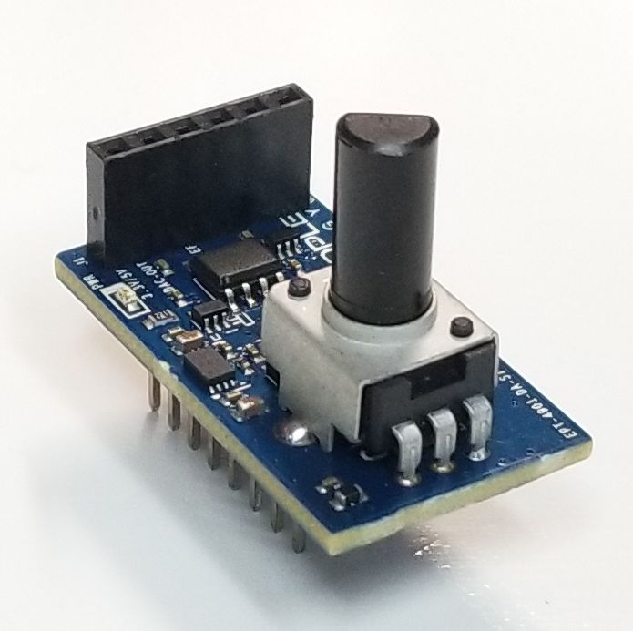
EPT-4901-DA-S1 DAC Board
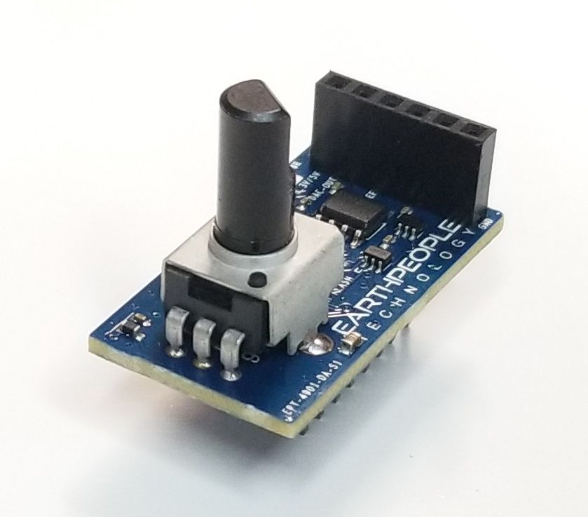
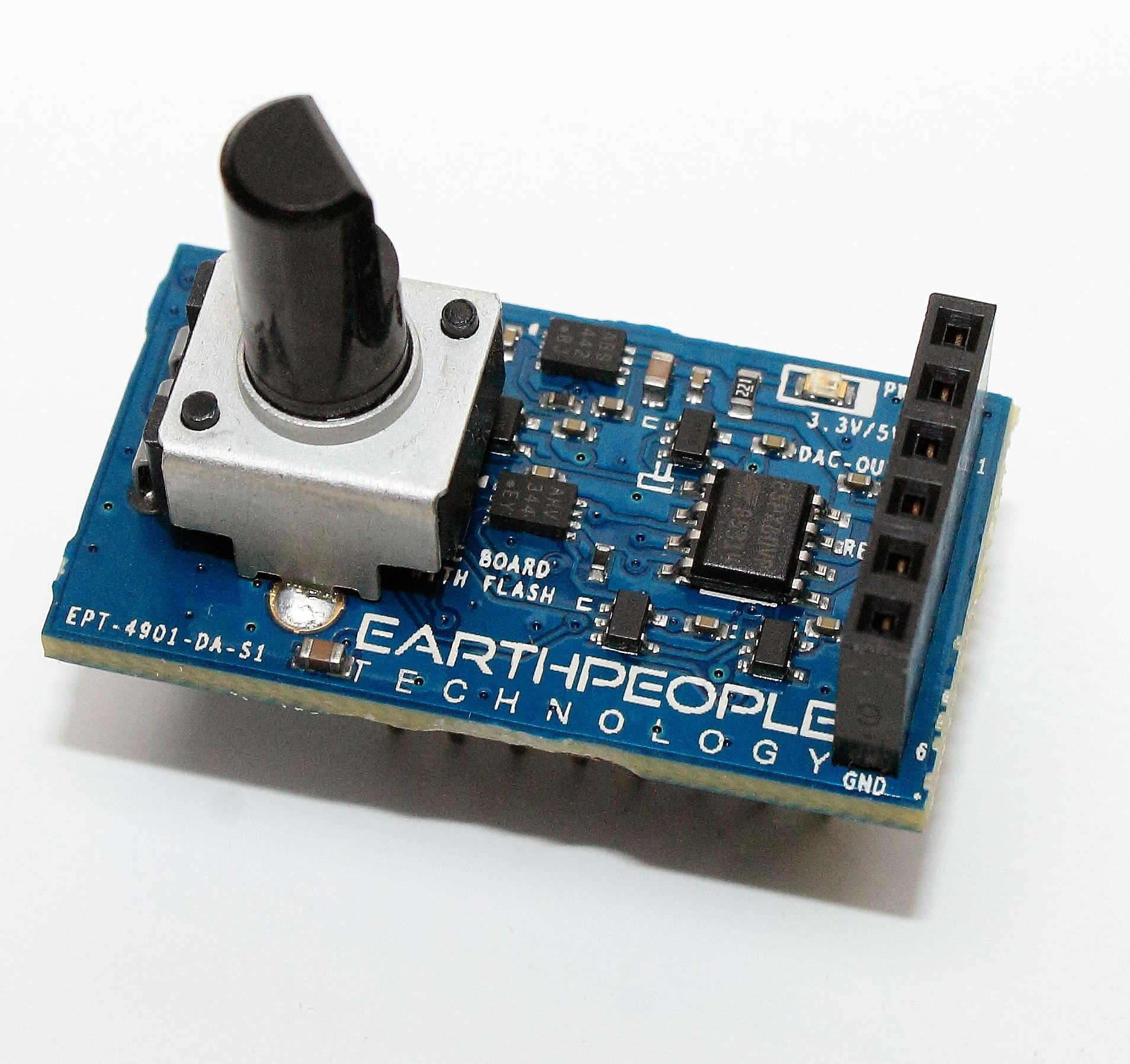
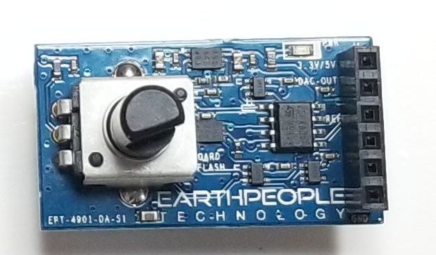
EPT-4901-DA-S1
Digital To Analog Converter Board
The EPT-4901-DA-S1 is an easy to use
DAC Board. It includes
an eight bit DAC and convinient
Bread Board connections
Purchase at these webstores:
| This DAC board features the MCP4091 Eight bit Digital to Analog chip. It is designed to fit into a bread board and connect to any Arduino board. The chip operates from a single 2.7V to 5.5V supply with an SPI compatible Serial Peripheral Interface. So, it can accommodate the +3.3V and +5V Arduinos such as the Mini, Mini Pro, Nano. |

Hardware Features:
|
| The EPT-4901-DA-S1 contains a MCP4091 DAC chip. The board can be used to generate any analog voltage from ground to VREF. VREF is determined by a voltage divider using a potentiometer. The potentiometer allows VREF to vary from zero volts to VCC. VCC is determined by the voltage used to power the EPT-4901-DA-S1. The DAC will accept any input digital value from zero to 255 and convert this value to analog. However, VREF determines the step size of each digital value. |
Digital to Analog Converter
| The MCP4901 is a single channel 8-bit buffered voltage output Digital-to-Analog Converter (DAC). The devices operate from a single 2.7V to 5.5V supply with an SPI compatible Serial Peripheral Interface. The user can configure the full-scale range of the device to be VREF or 2*VREF by setting the gain selection option bit (gain of 1 of 2). The device be can shut down by setting the Configuration Register bit. In Shutdown mode, most of the internal circuits are turned off for power savings, and the output amplifier is configured to present a known high resistance output load (500 kΩ typical). The device include double-buffered registers, allowing synchronous updates of the DAC output using the LDAC pin. These devices also incorporate a Power-on Reset (POR) circuit to ensure reliable powerup. The device utilizes a resistive string architecture, with its inherent advantages of low Differential Non-Linearity (DNL) error and fast settling time. This device is specified over the extended temperature range (+125°C). |
VREF Potentiometer
| The EPT-4901-DA-S1 board includes a 20K potentiometer. This pot forms a voltage divider with a second resistor to vary the voltage applied to VREF. This varied voltage provides an amplitude control for the Analog Out voltage. |
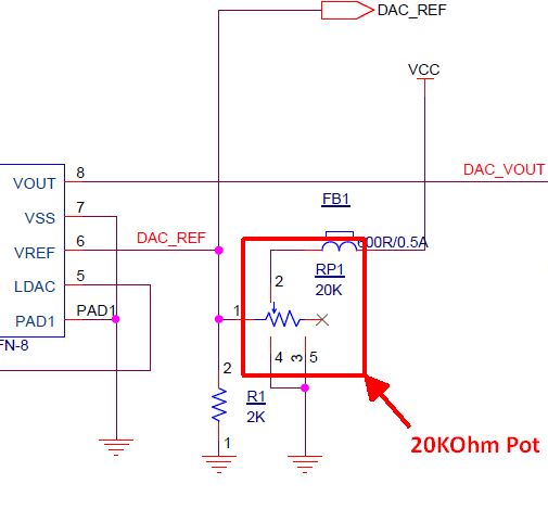
| By varying the VREF, the accuracy of the DAC can be improved. This is because the analog output step size between each DAC digital word is reduced. For example, if the VREF is set to 5V, the analog output step size is 5V/256 (Digital Steps) = 0.0195V per step. If the VREF is set to 2.5V, the analog output step size is 2.5V/256 (Digital Steps) = 0.00976V per step. The smaller the analog step size (or quanta), the more accurate the analog signal can be. |
Downloads
| 85-000010 | MCP4901 Digital To Analog Converter Board User Manual | EPT_4901_DAC_UM.pdf |
| 95-000010 | MCP4901 Digital To Analog Converter Board Data Sheet | EPT_4901_DAC_DS.pdf |
| 45-000010 | MCP4901 Digital To Analog Converter Board Project DVD | EPT-4901-DAC-PROPJECT_DVD |
| 55-000010 | MCP4901 Digital To Analog Converter Board Schematics | EPT_4901_DA_SCHEMATICS.PDF |
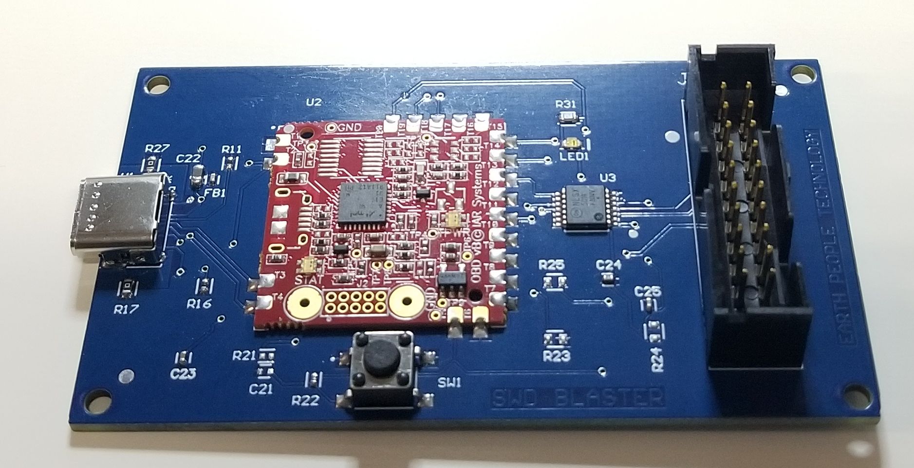
SWD Blaster MCU Programmer

|
SWD BLASTER The SWD Blaster is an easy to use |
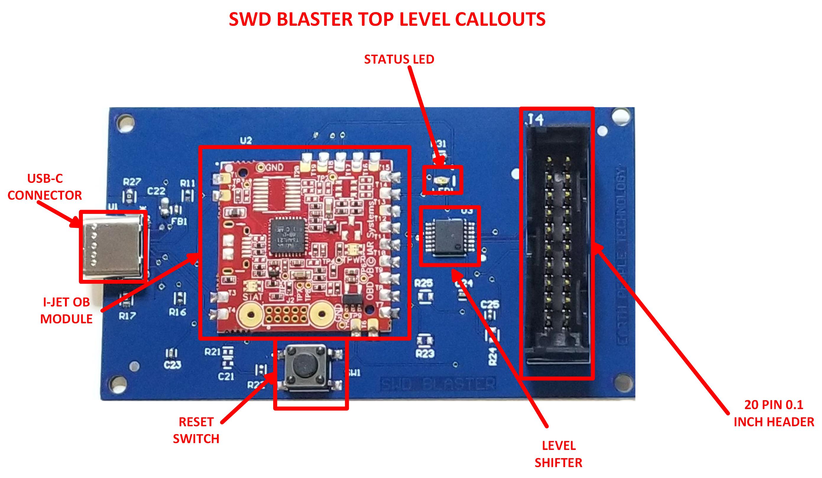
| The SWD Blaster is a stand alone programmer for use with IAR Embedded Workbench and capable of debugging most ARM MCU’s. It includes the I-Jet On Board Module from IAR. The SWD Blaster has a maximum speed of 8MHz. I-jet provides a fast debugging platform via JTAG and SWD/SWO with download speeds of up to 1.89 MByte/sec and support for SWO speeds of up to 60MHz. |
Hardware Features:
|
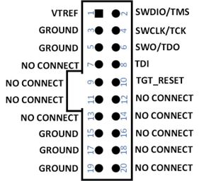
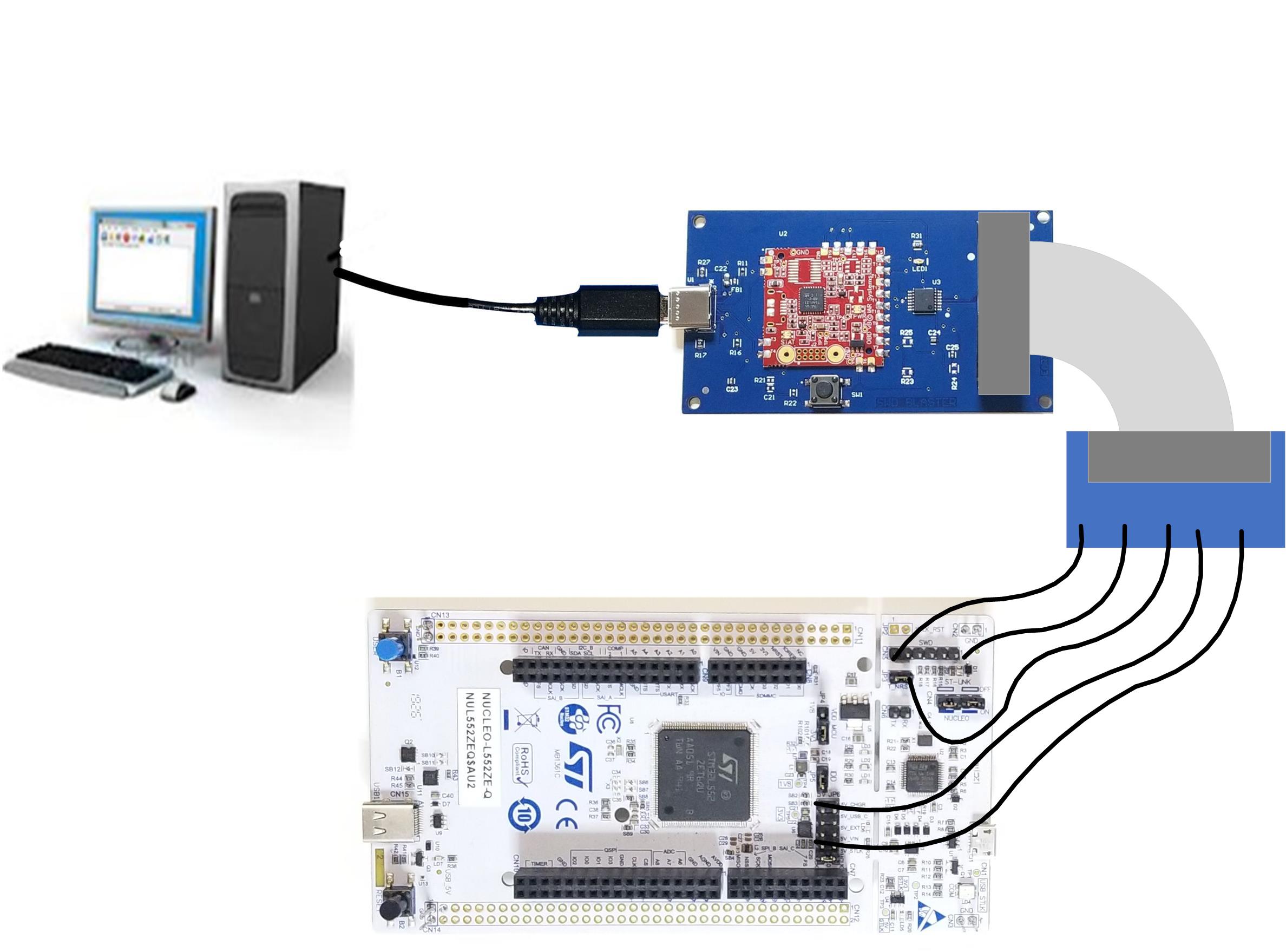
| The board is powered by USB and connects to target MCU’s via the 20 pin 0.1 Inch header. The SWD Blaster does not require a license. The USB driver for the board is included in the IAR Embedded Workbench software. The board is plug and play and includes a reset pushbutton switch to reset the target. |
Programming ARM MCUs
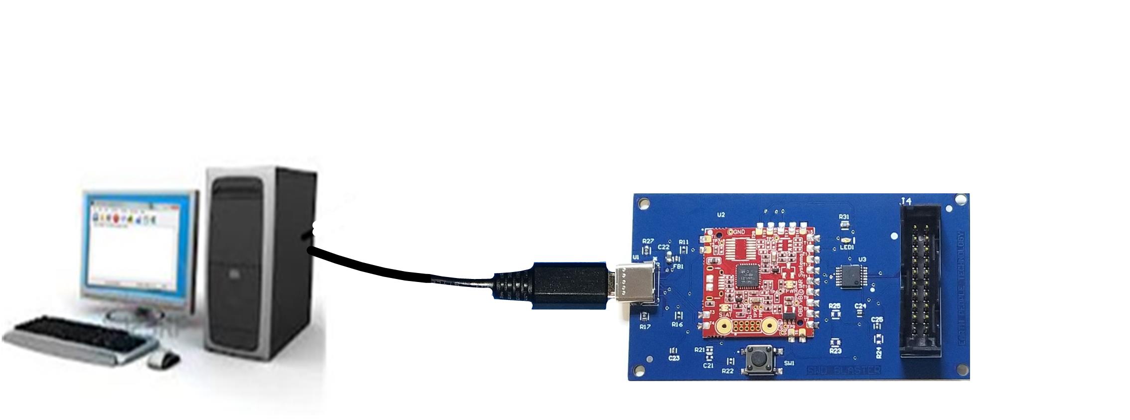
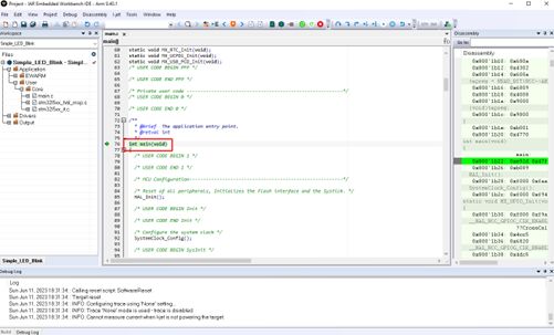
| The SWD Blaster must have the IAR Embedded Workbench installed on the PC. The USB driver is included in the software. Once installed, connect the SWD Blaster using a USB-C cable. Connect the USB cable to a port on the Host PC. Connect the SWD Signals to the target MCU. Use the Embedded Workbench software to connect to the target board. |
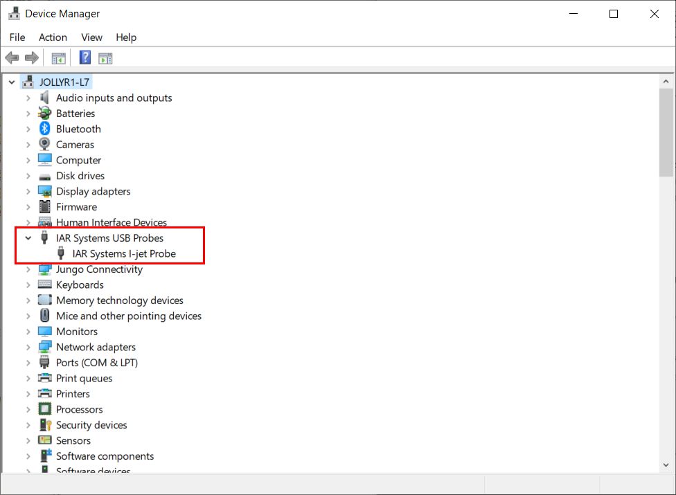
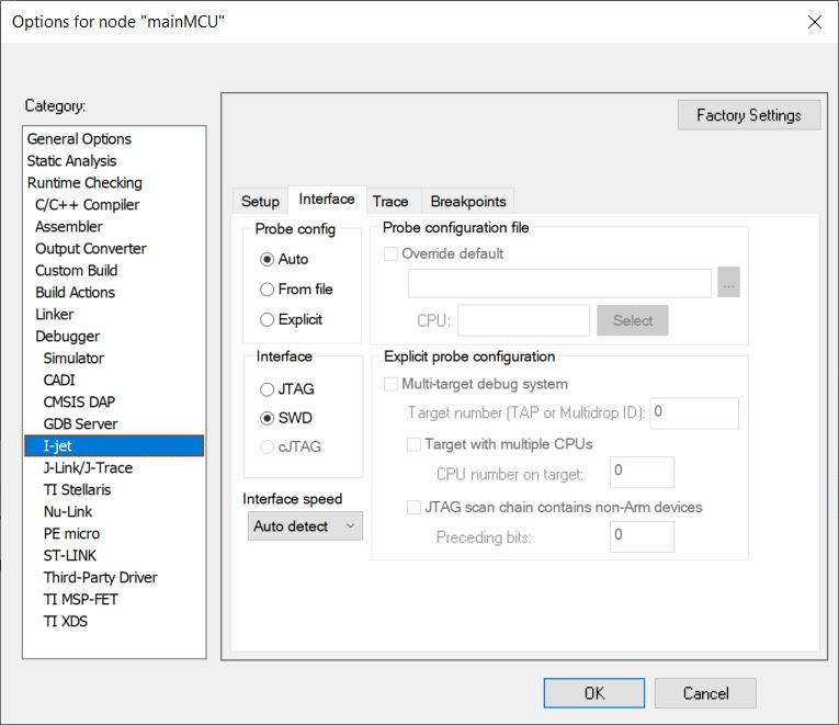
| The SWD Blaster will show up under Device Manager as the I-Jet. When the Embedded Workbench software is open, the user can select I-Jet from the Options Window of the user project. Write user code, compile, download and start debugging. |
SWD Blaster Functionality
| The SWD Blaster provides the full functionality of the Embedded Workbench software. The user can Download, Debug, Step Go, Pause execution of user code. The OBM provides full SWD JTAG in circuit emulation. The emulation speed is limited to 8MHz. However, this speed is more than adequate for most applications. The OBM provides all of the debugging power of the IAR Embedded Workbench. The user can:
|
Getting Started with Microcontrollers Made Easy
| The SWD Blaster comes with a User Manual that walks the user through getting started with their first Microcontroller (MCU) project development. The User Manual explains how to get the free version of IAR Embedded Workbench and download and install onto the users PC. |
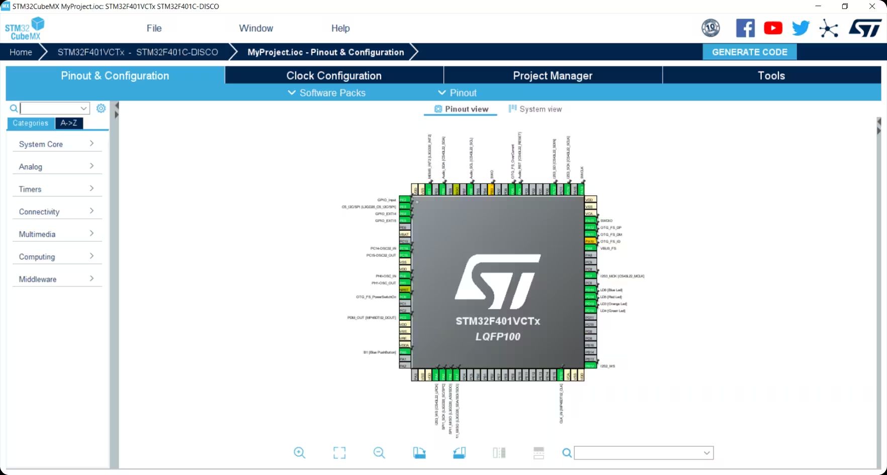
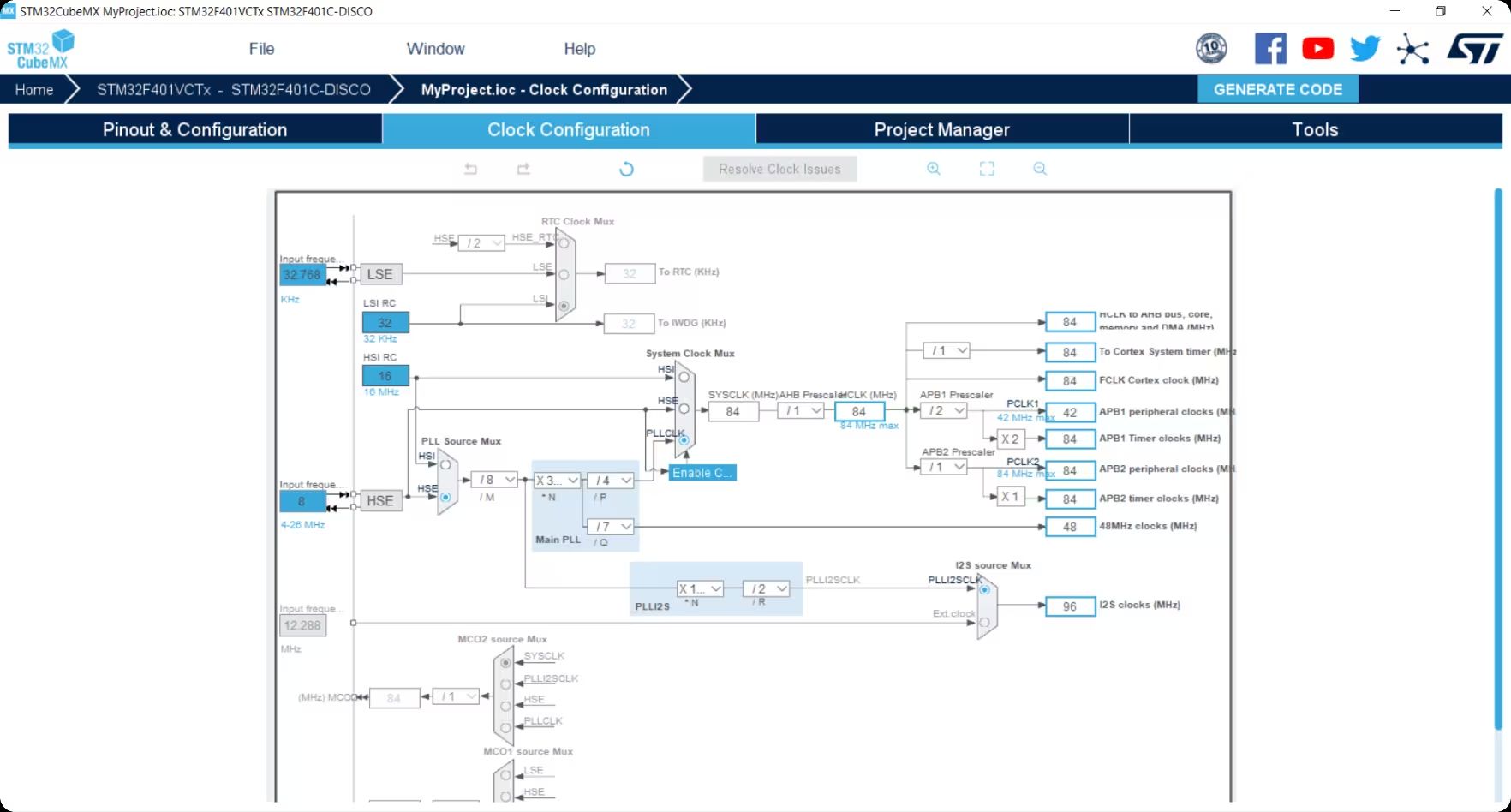
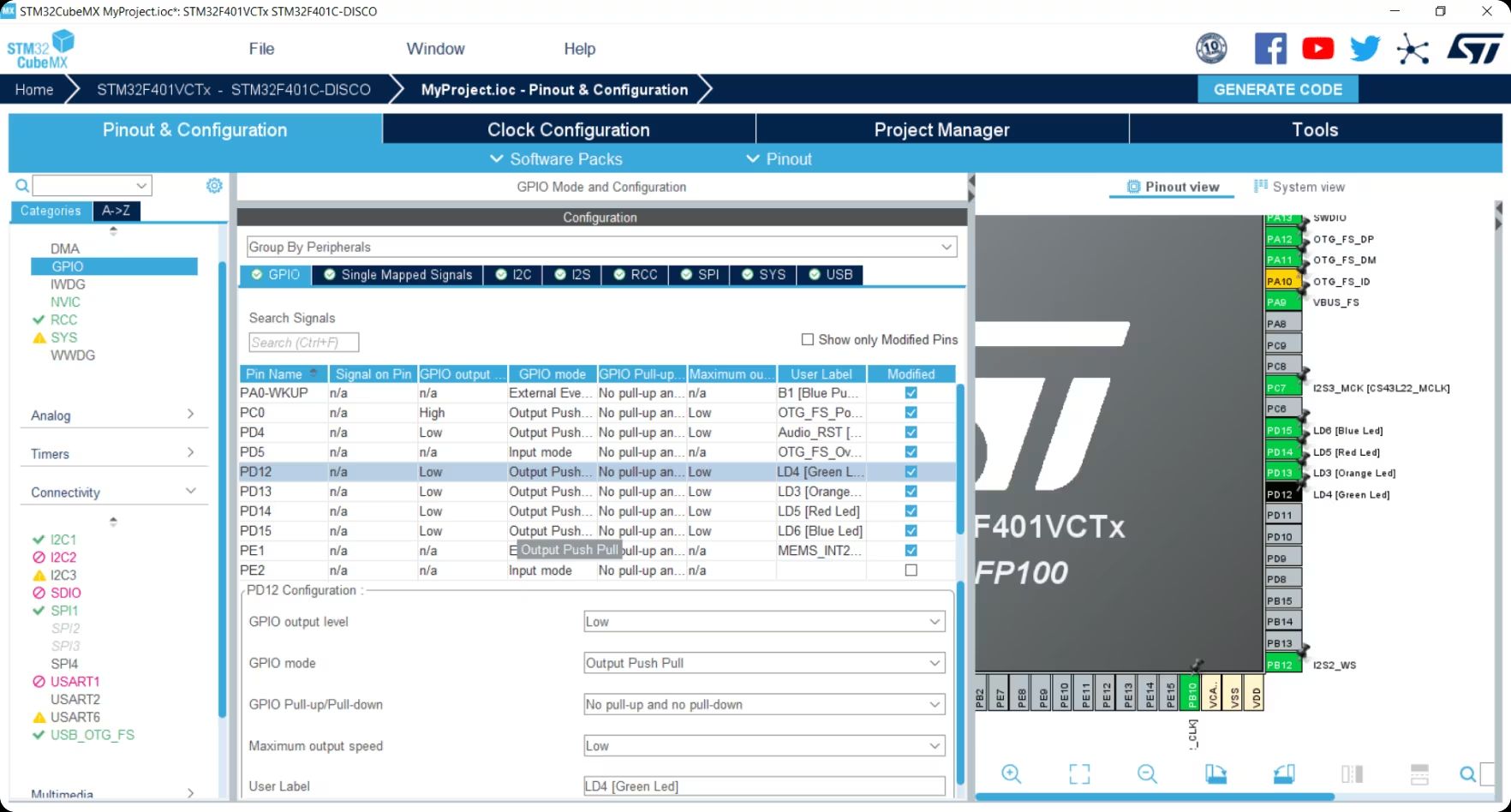
| The User Manual will show to the user how to use Board Support Package such as STM32CubeMX. This software provides a graphical tool that allows configuring the STM32 microcontrollers very easily and generate a complete C project for IAR. STM32CubeMX is free for users. The manual will walk the user through download and install process. Then, it will explain how to set up your first ARM MCU project, GPIO selection, Clock configuration and Peripheral configuration. |
ARM Code Development
| The SWD Blaster User Manual provides an introduction to getting the user set up and working with their first ARM MCU project. After setting up the project using a BSP (Board Support Package), the manual walks the user through how to open a project in IAR EW. The user will make modifications to the default project. The user is instructed to blink an LED attached to a GPIO on the MCU. The manual will explain how to compile the user code, download the code and start the debug process on the target MCU. The User Manual explains the basic features of the debugger environment. It explains the use of breakpoints, watch variables and variable search. The SWD Blaster and User Manuals, Data sheets and example projects will expertly assist getting even the most basic user up and running with their first ARM Code Project. |
Downloads
| 85-001000 | SWD Blaster MCU Programmer User Manual | EPT_SWD_BLASTER_UM_V6.pdf |
| 95-001000 | SWD Blaster MCU Programmer Data Sheet | SWD_BLASTER_DS_V2.pdf |
| 45-001000 | SWD Blaster MCU Programmer Project DVD | SWD_BLASTER_MCU_PROJECT_1.0_DVD |
| 55-001000 | SWD Blaster MCU Programmer Schematics | EPT_IOBM_PT_W2_V1.SCHEMATIC.PDF |
| 35-001000 | SWD Blaster Drivers | CDM212364_Setup.ZIP |
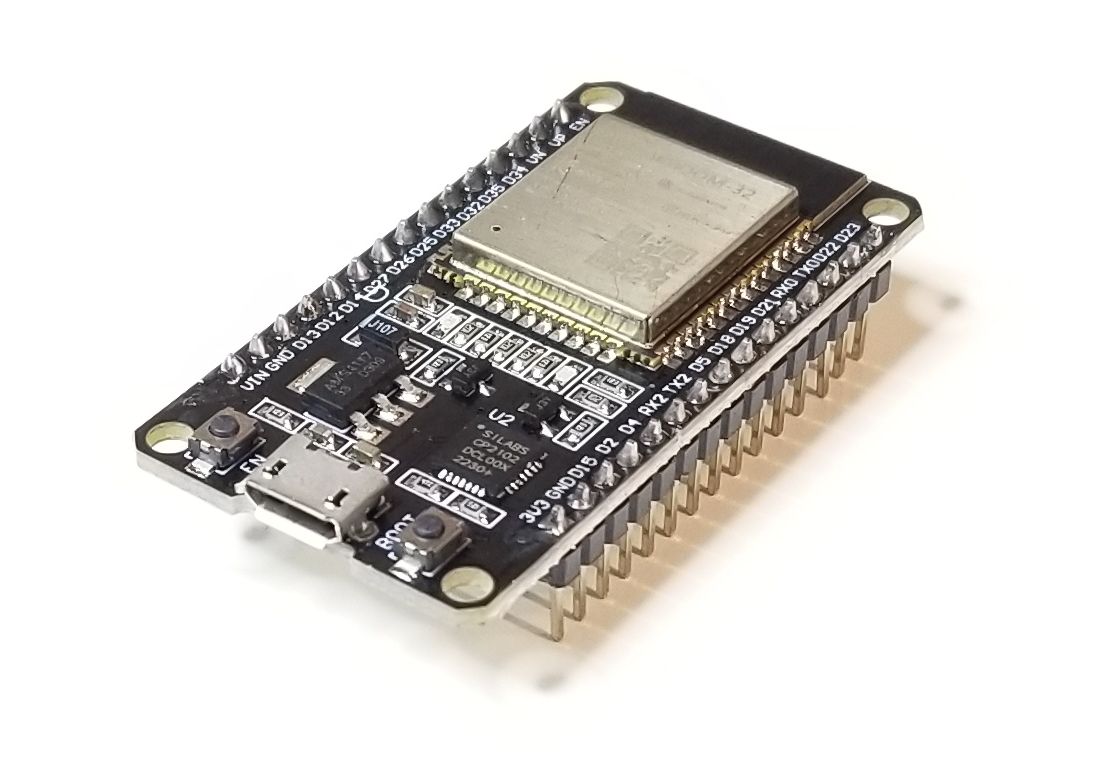
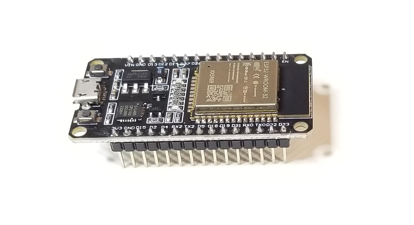
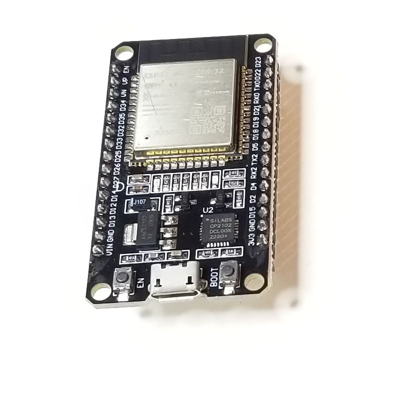
ESP32 WROOM DEVELOPMENT BOARD
|
ESP32 WROOM The ESP32 is an easy to use |
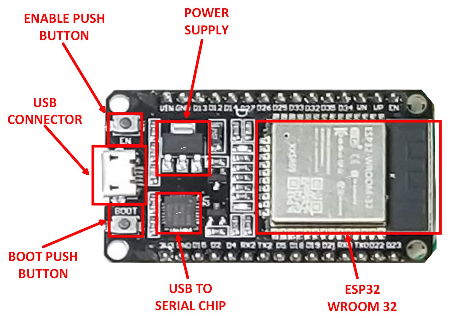
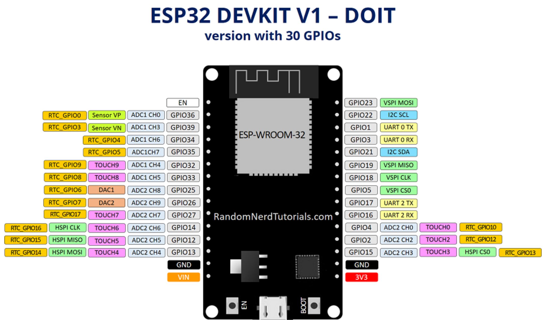
| The ESP32 Development Board is a board created around ESP32 WROOM 32 chip containing voltage regulator and USB programmer circuit for ESP32 chip, and a few many other features. For application development there is a choice between Arduino IDE or ESP-IDF (Native platform). Mostly users choose the Arduino IDE because of its simplicity and compatibility. ESP32 Development Board comes with a pre-installed firmware which allows to work with the interpreted language, sending commands through the serial port (CP2102 USB to Serial chip). The ESP32 Development board is specially designed to work on breadboard. It has a voltage regulator that allows it to feed directly from the USB port. The input/output pins work at 3.3V. The CP2102 chip is responsible for USB to serial communication. |
Hardware Features:
|
MCU + Wifi + BLE
| The board functions as a 32 MCU and provides all peripherals expected from an MCU. It also includes a Wifi transceiver unit and a BLE 4.2 Radio. All of this functionality is easily accessed through the Arduino IDE. An easy to use, intuitive software interface to build your software programs such as Weather Station, Indoor Asset Tracking, Robotics and much more. |
Programming The ESP32 MCUs
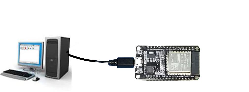
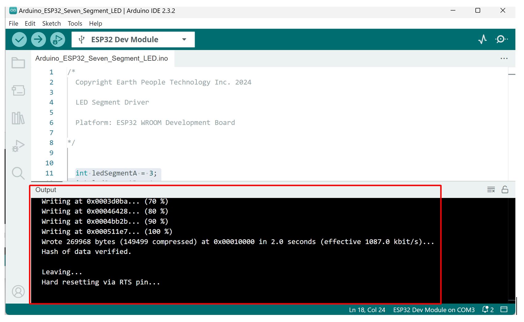
| Programming the ESP32 with User Software is easy using the Arduino IDE. The ESP32 WROOM Development board includes a USB to Serial chip. Just connect the board to an open USB Port on your PC using a Micro-B cable. Then open the Arduino IDE software, select the board from the library. Write your software, then hit the “Upload” button. It’s as easy as that. |
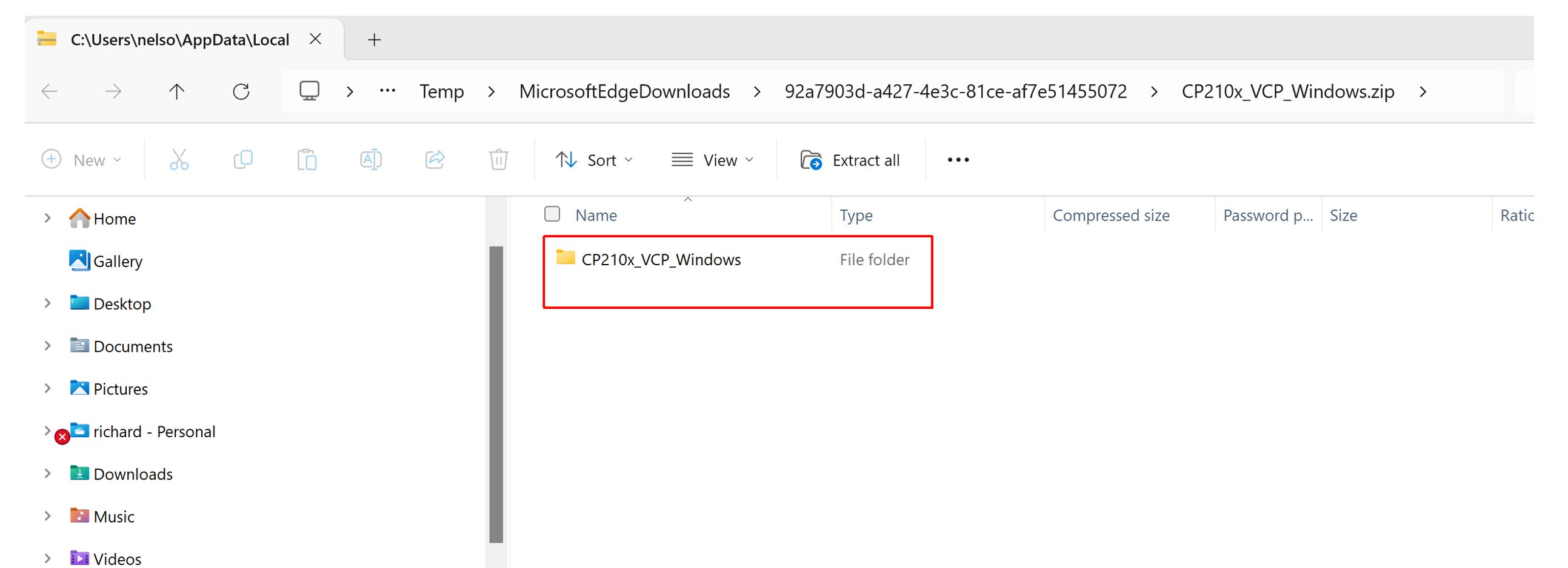
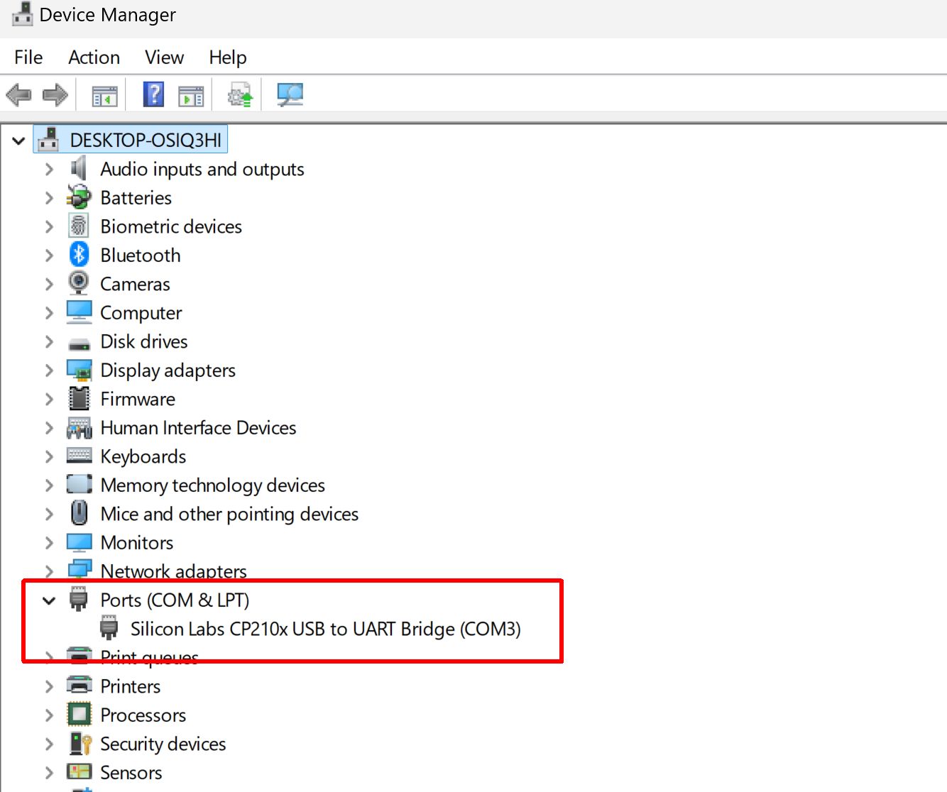
| When the ESP WROOM Development Board is connected to an open USB Port the USB driver for the CP2109 chip is loaded. You will be able to see this chip under “Device Manager” as a COM Port. Once the ESP32 board appears as a COM Port, the Arduino IDE will be able to connect to it. |
Connecting the Arduino IDE to ESP32
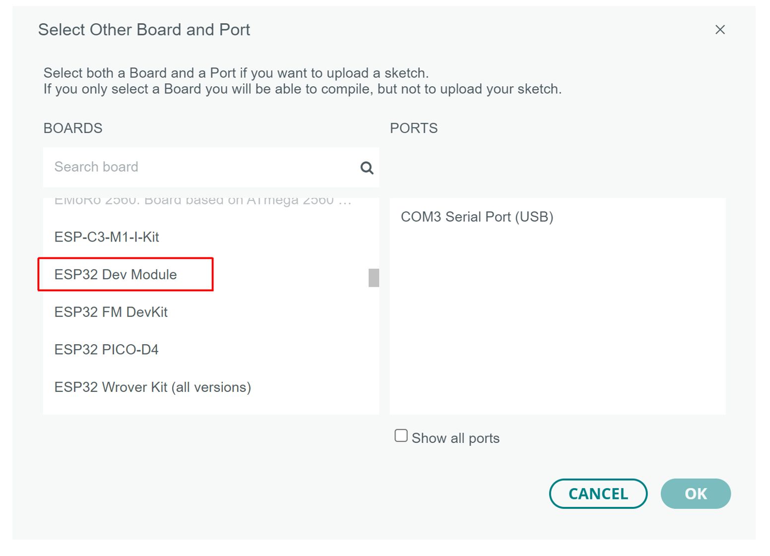
| Once the ESP32 board is connected and the driver is loaded, Open the Arduino IDE, then click on the “Boards Manager” button and search the left side of the Window for the ESP32 Libraries. Click on “Install” and the software will automatically install all the available libraries for several ESP32 Development boards. |
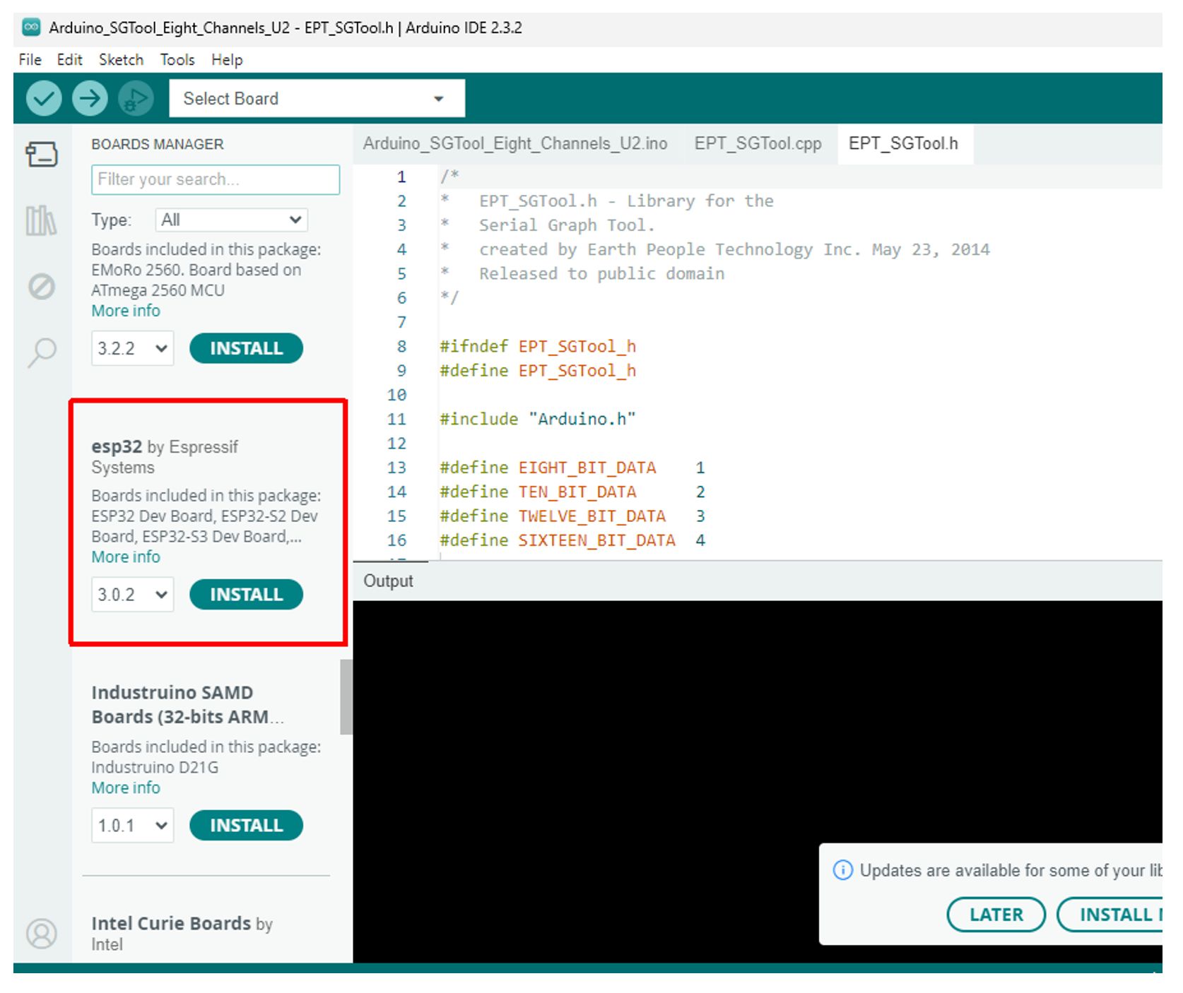
| Once all the ESP32 libraries are installed, you can go Tools->Board and select the “ESP32 Dev Module”. Then go to Tools->Port and select the COM Port that the ESP32 WROOM Development board is attached to. With these items selected, you can now write and execute your own code. |
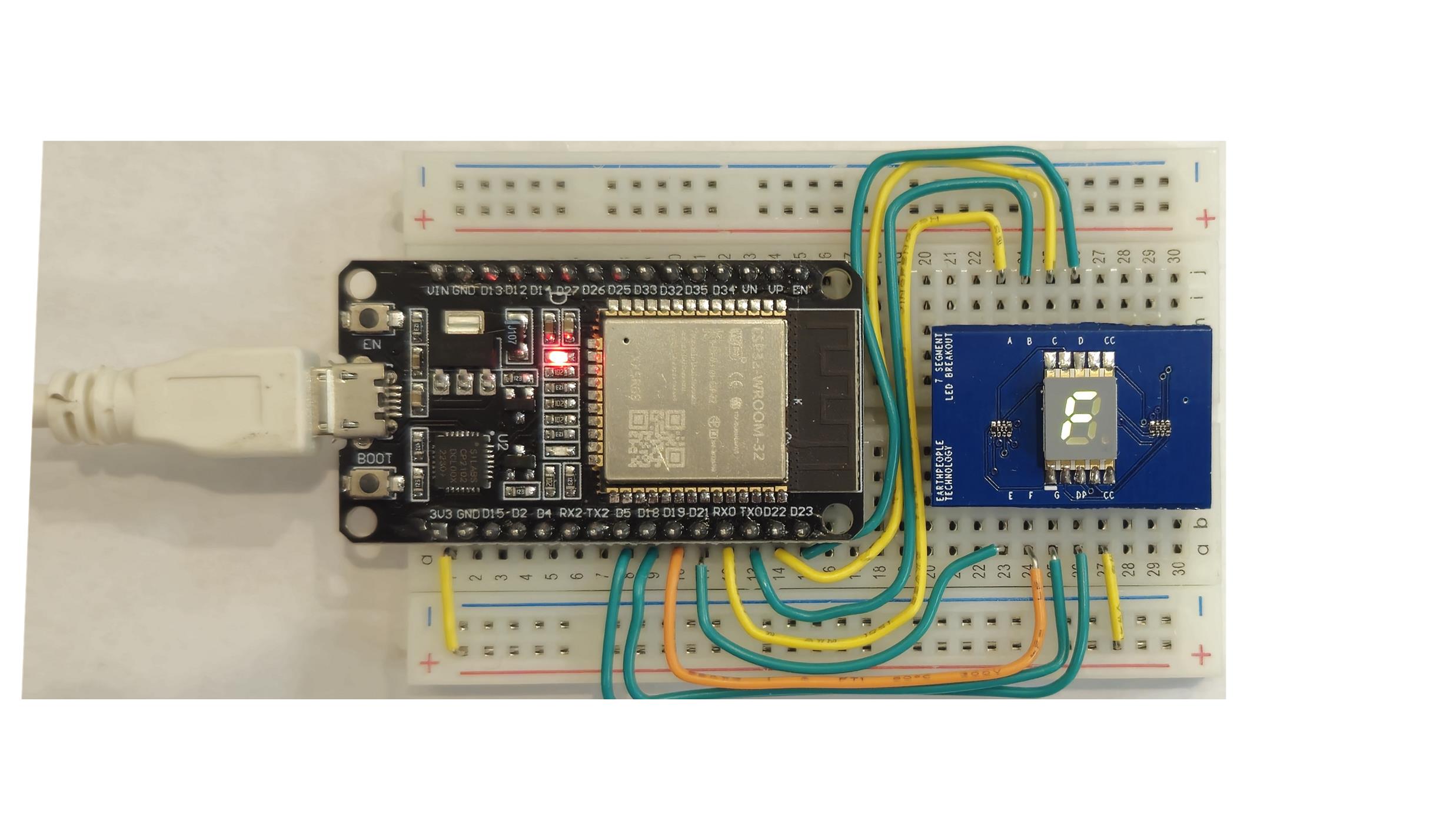
| The User Manual will show to the user how select one of the pre-compiled sample programs and load it, compile it and upload it to the ESP32 MCU. The User Manual will show the user how to build the projects using a bread board, ESP32 WROOM Development Board, Wire Kit and Device (Such as LED RGB. Breakout Board or Seven Segment LED Display Board). |
ESP32 Code Development
| With your first programmed loaded and working on to the ESP32 WROOM Development Board completed, you can start on more advanced projects. More advanced projects will include getting started with WiFi. There are several pre-compiled WiFi projects under the Arduino ESP32 Examples. These examples are easy to use. Just open the sketch, upload and start examining the results. The ESP32 WROOM Development Board is a complete Development Kit that is easy to get started, easy to develop code and easy to get advanced projects perfected. This kit is great for beginners, great for intermediate programmers, and great for advanced projects. |
Downloads
| 85-001020 | ESP32 WROOM Development Board User Manual | ESP32_WROOM_DEV_BOARD_UM_V3.pdf |
| 95-001020 | ESP32 WROOM Development Board Data Sheet | ESP32_WROOM_DEV_BOARD_DS_V2.pdf |
| 45-001020 | ESP32 WROOM Development Board Project DVD | ESP32_DJ_SNACK_PACK_PROJECT_4.0_DVD |
| 55-001020 | ESP32 WROOM Development Board Schematics | ESP32-Core-Board-V2_sch.PDF |
| 35-001020 | ESP32 WROOM Development Board Drivers | CP210x_VCP_Windows.ZIP |