BeeProLogic CPLD Development Board

The BeeProLogic is an Easy To Use
Beginners CPLD Development Board.
BeeProLogic CPLD Development Board
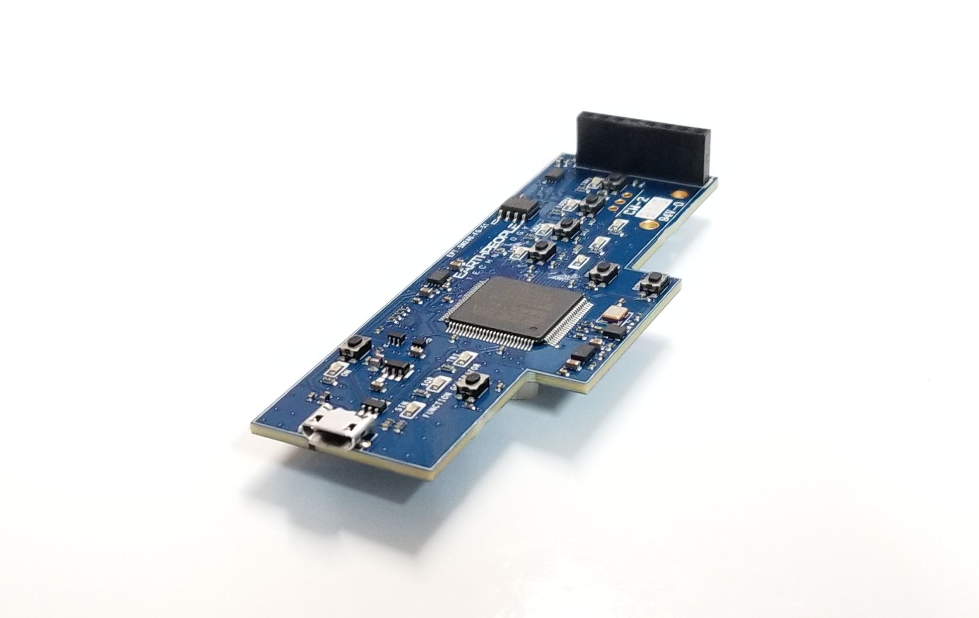
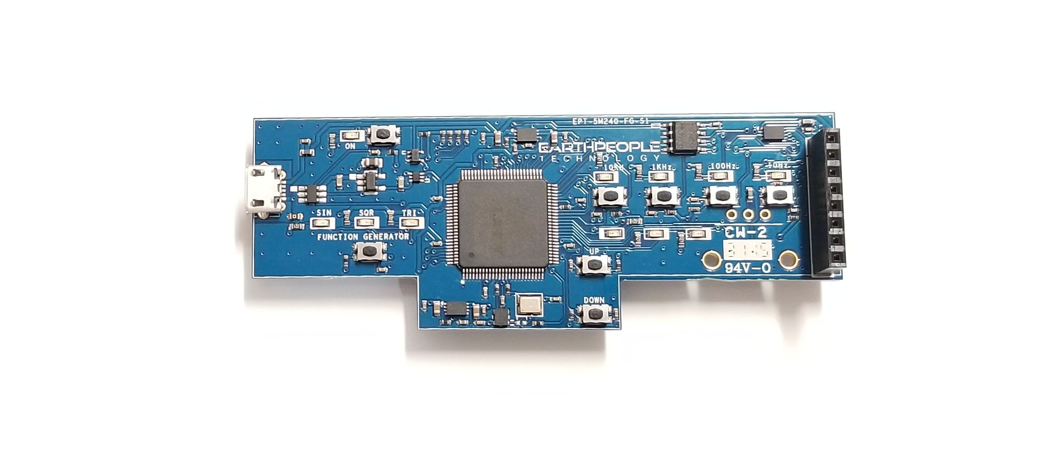
| The BeeProLogic is a CPLD development board that is designed to be user friendly and a great introduction into digital design for Electrical Engineering students and hobbyists. This board provides a simplified method for debugging programmable logic code. It has been designed with plenty of LEDs and Pushbuttons to allow a large amount of interaction between user and hardware operations. |
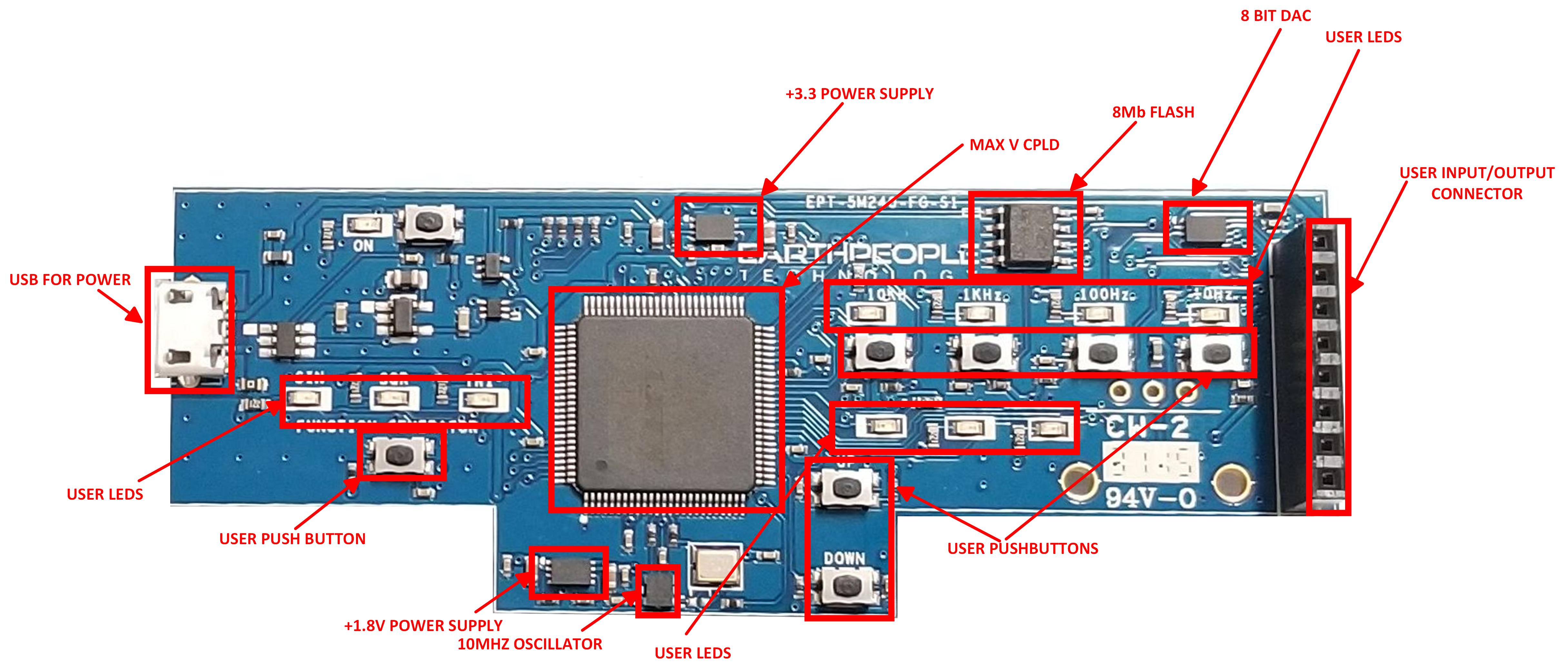
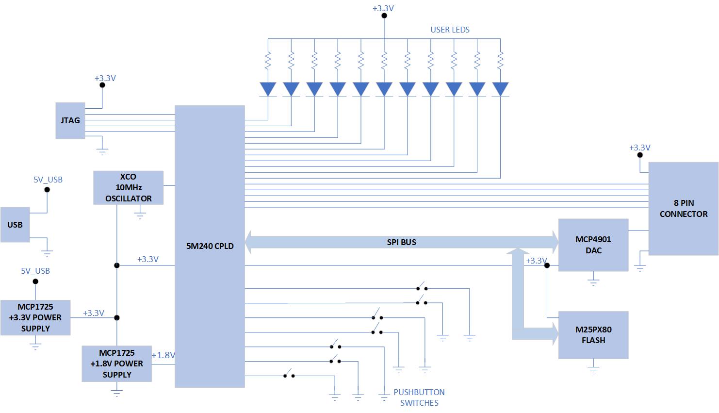
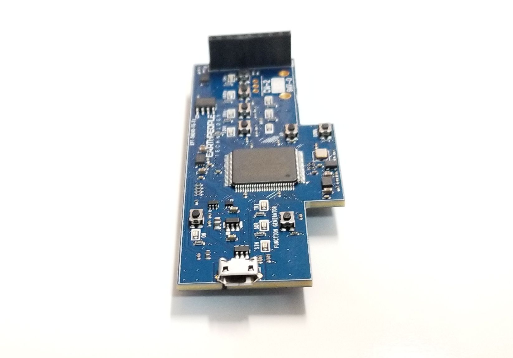
| The Earth People Technology BeeProLogic CPLD development system hardware consists of a a CPLD, 8Mb Flash and a single channel DAC. The board requires an external JTAG Programmer compatible with the JTAG Blaster. The Core of the board is the MAX V chip. The board can be powered by standard USB Micro B connector. There is a 10MHz oscillator attached to the MAX V chip for clocking user code. The board also includes 10 Green User LEDS, Seven User Pushbuttons and One external connector with six pins for GPIO. |
Hardware Features:
|
Simplified Development Board
| The BeeProLogic DVD provides detailed step by step instructions to quickly guide the user to create a project, synthesize the project and download the programming file into the CPLD. The Quartus Prime Software must be downloaded from Intels website. Once the Quartus software is on your desktop, the guide will show you how to create a project, write you first LED blinky code, compile and program the CPLD. |
Programming the BeeProLogic Board
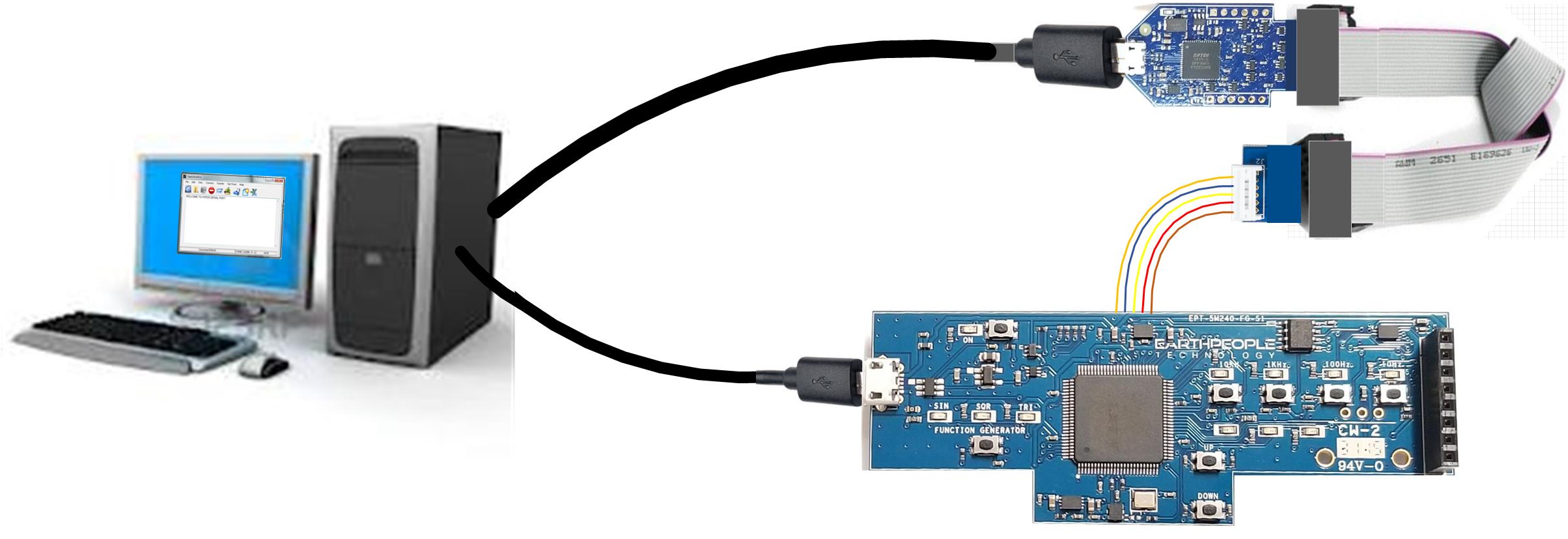
| The CPLD on the BeePro can be programmed with the code created by the user. Programming is quick and easy. The BeeProLogic Does Not Include An OnBoard programmer. The user must purchase a separate JTAG Blaster. To program the board, a standard USB Micro-B cable must be connected from power (USB Port on laptop) to the board. Then connect the JTAG Blaster to a USB Port on a laptop. Use the provided adapter to connect the JTAG Blaster 10 pin connector to the 6 pin. 2mm pitch connector. Connect the 6 pin 2mm pitch connector to the BeeProLogic connector on the back of the board. |
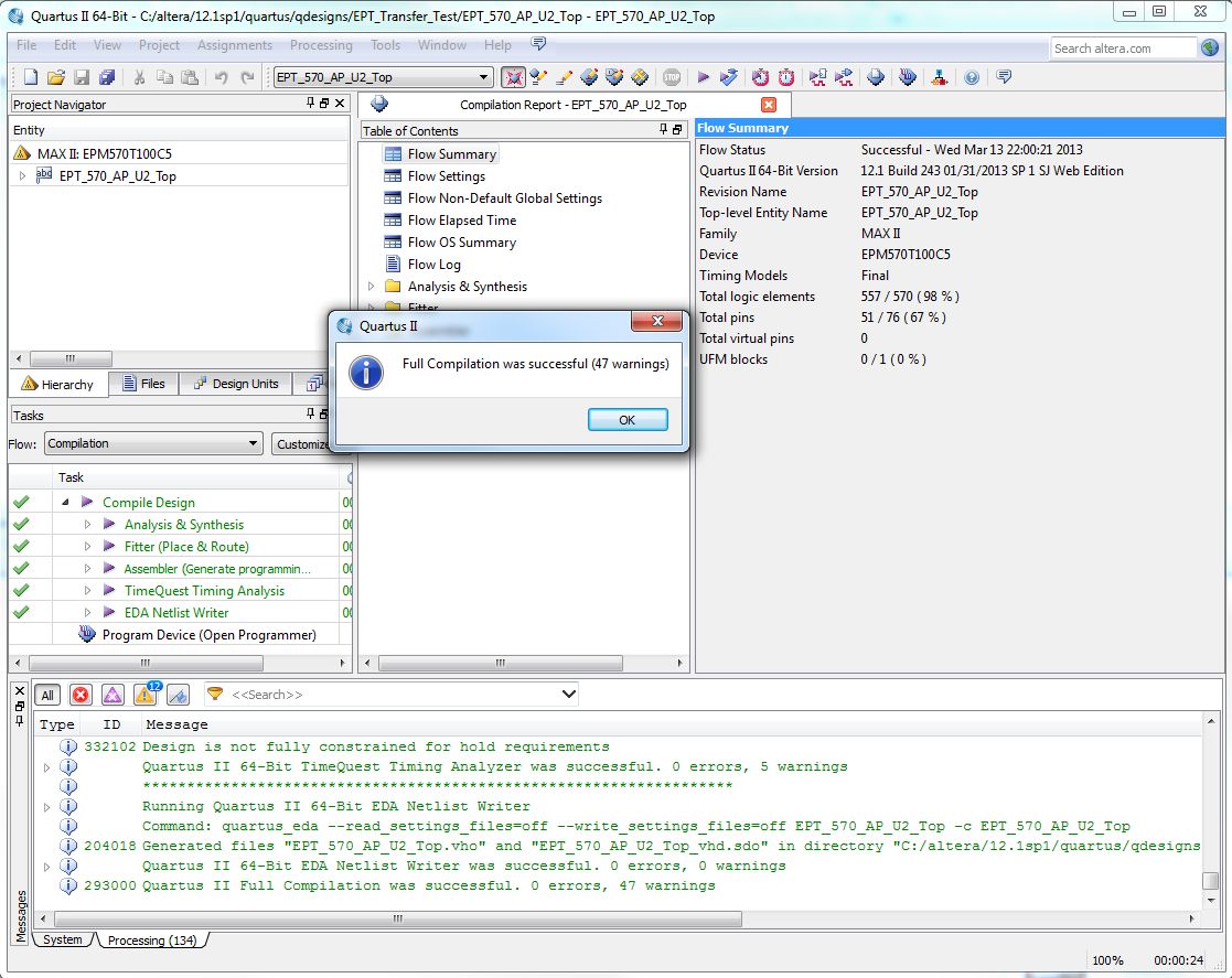
| Use the Quartus Prime Software Tools to program the 5M240 CPLD on board the BeeProLogic. The User Manual includes step by step instructions on building the user project. It includes the steps to successfully program the CPLD. |
Controlling The Board
The User LEDs
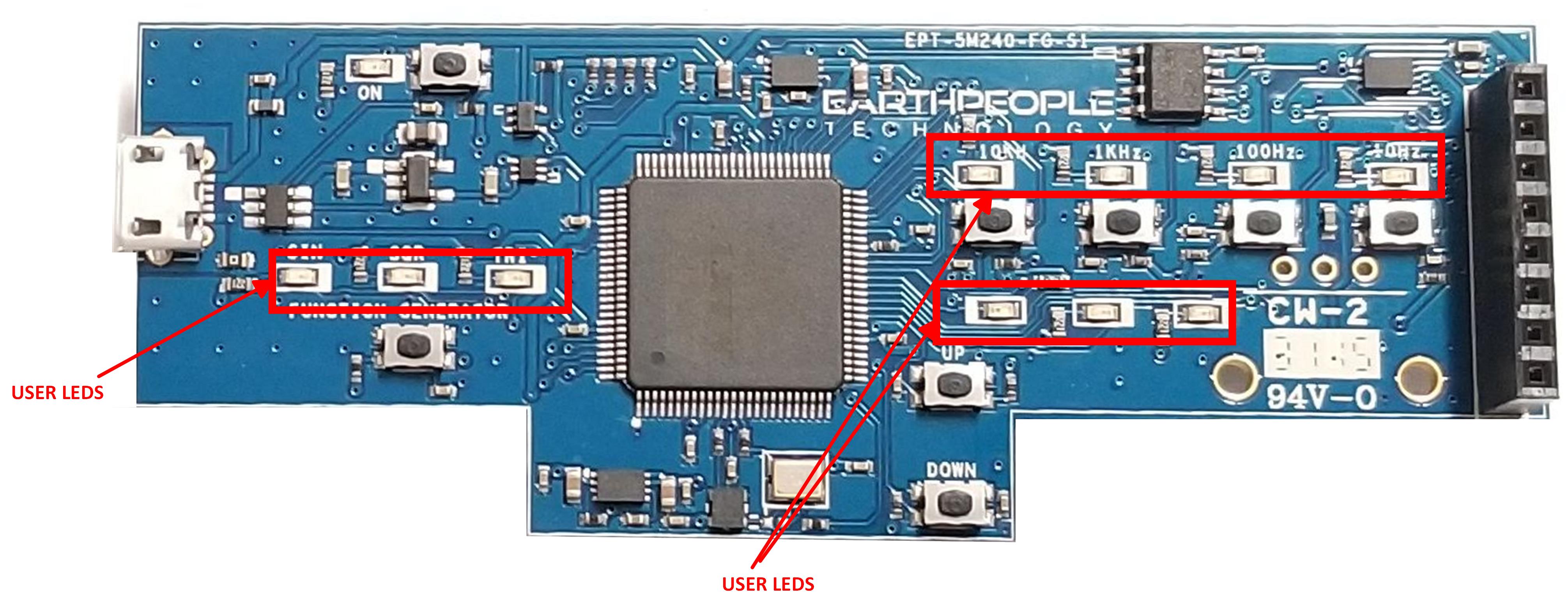
| The BeeProLogic includes eleven user LEDs. The LEDs are directly sinked from the CPLD with the anode connected to +3.3V. This voltage is used to meet the forward voltage along with a 220 Ohm series resistor for each LED. The resistor provides the series current through the LEDS and controls the brightness. |
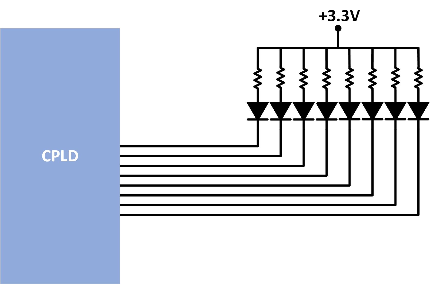
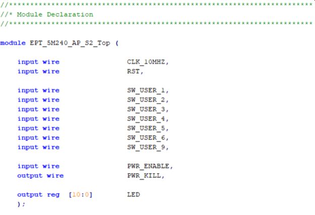
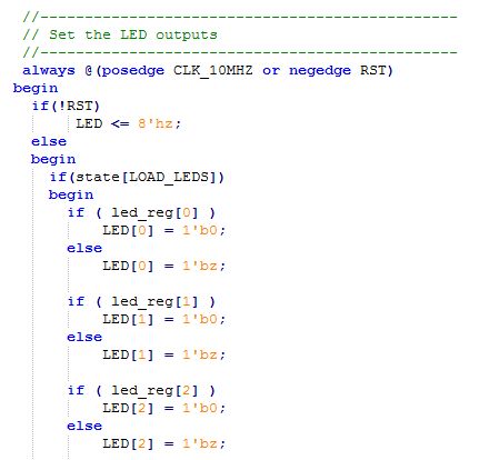
| The code to drive the LEDs is either zero (1’b0) or floating (1’bz). First, declare the LED as an output. In the example below, the vector LED is set to ‘reg’ because it is driven in an always block. |
| To turn the selected LED on, set the signal equal to 1’b0. This will apply a ground to the cathode side of the LED and allow current to flow through the circuit turning the LED on. To turn the selected LED off, set the signal equal to 1’bz. This will float the cathode side of the LED and no current will flow through the LED. |
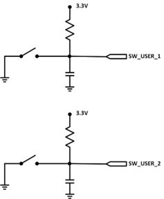
The User Pushbuttons
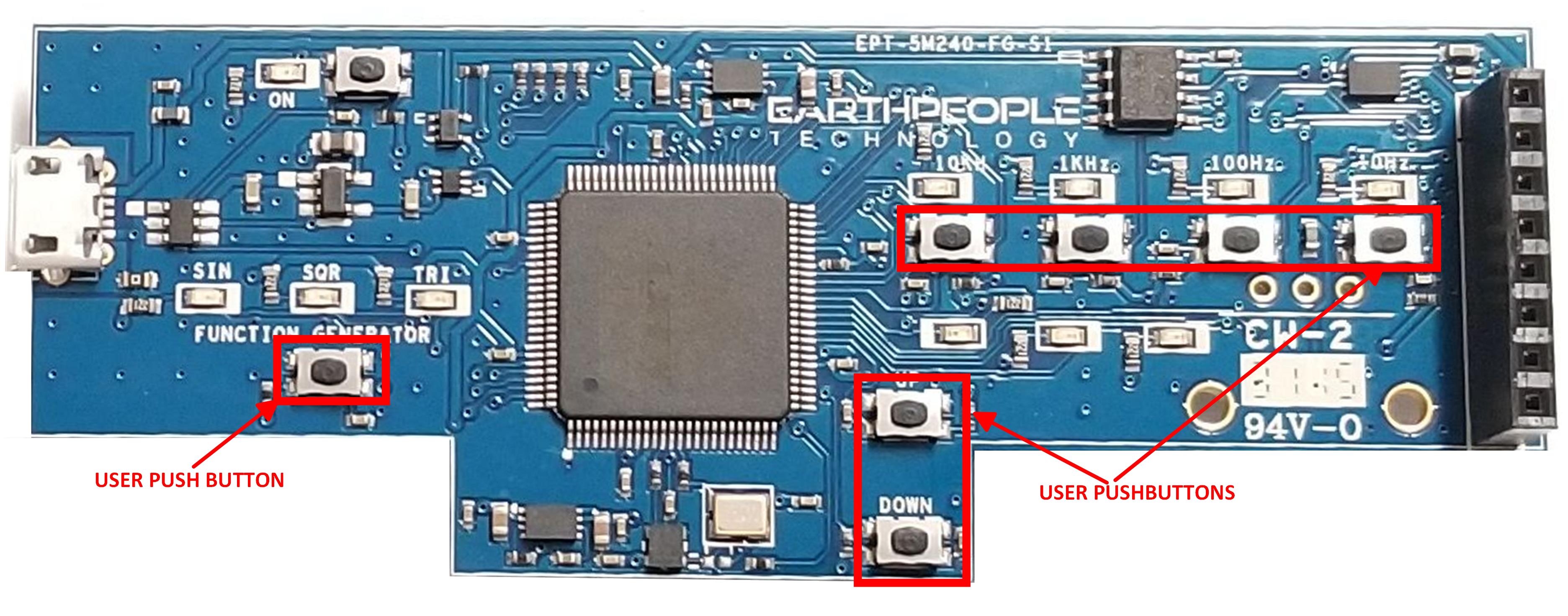
| The BeeProLogic includes eight push button switches. All are momentary contact switches. They include a 1uF cap to ground to debounce both switches. The code to use these switches is simple, just declare an input on the selected switch pin. Then use code to activate the a function with the input signal goes to low. |
The 8 Bit DAC
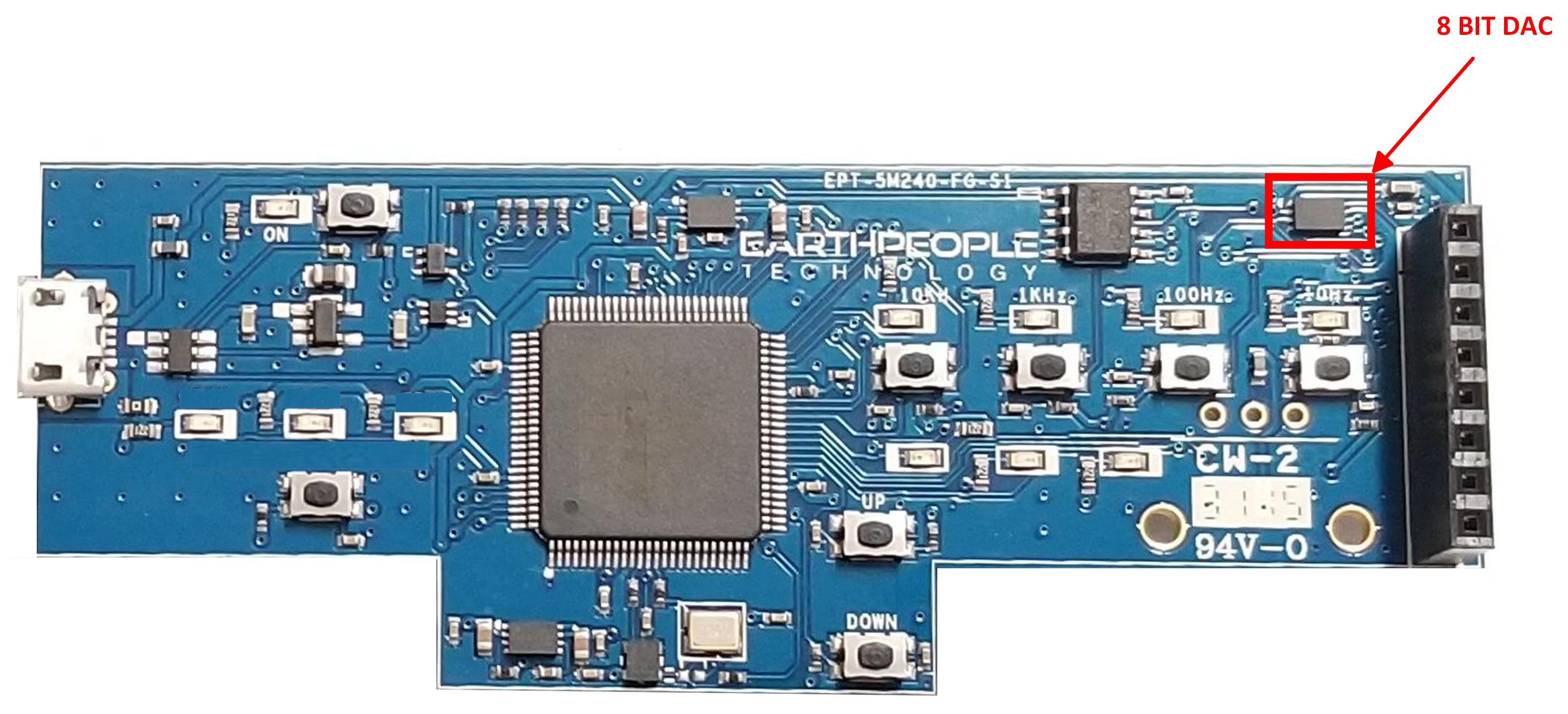
| The BeeProLogic includes a single channel 8 bit DAC. The user can write any 8 bit digital value to the DAC and the associated analog voltage will appear on the output. The DAC is directly connected to the CPLD. The communication path between CPLD and the 8 bit DAC is via SPI bus. |
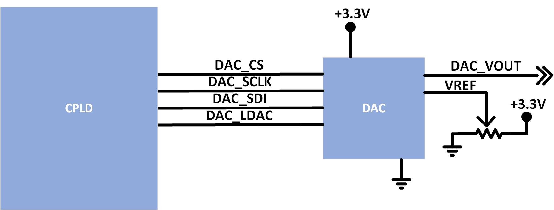
| TThe MCP4901 chip is an SPI Slave. Any SPI host can communicate with the chip at speeds up to 20 MHz. The chip has no minimum SPI clock speed. The chip will respond to any SPI slave at any clock rate as long as it does not exceed 20 MHz. |
User Inputs/Outputs
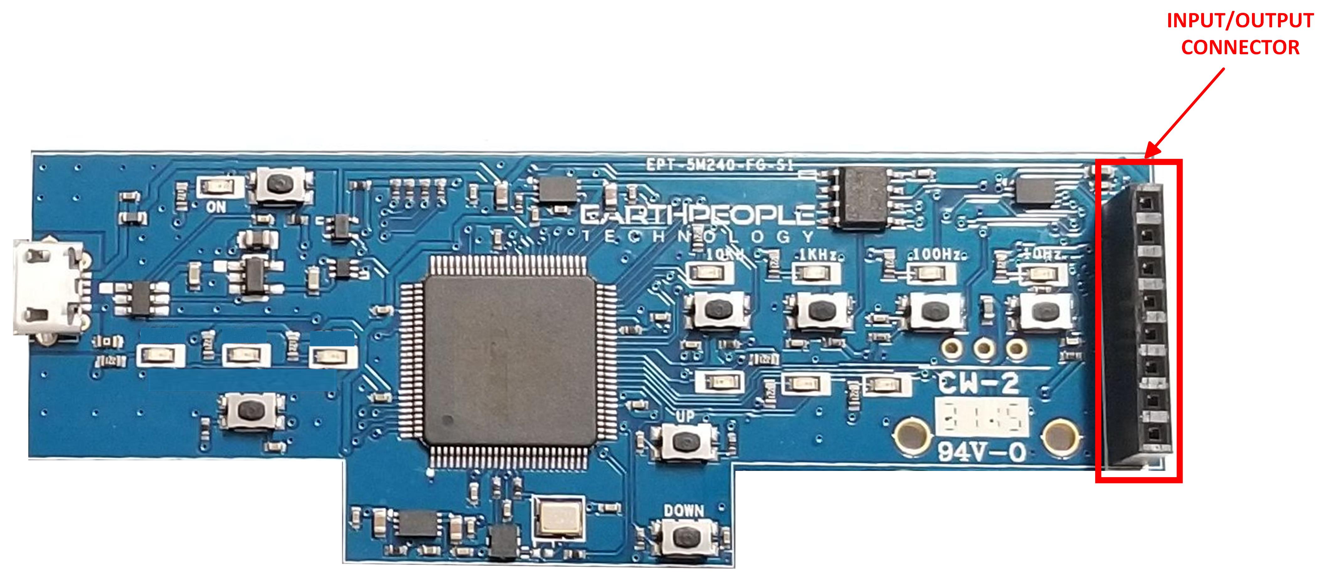
| The BeeProLogic has one 8 pin header that provide 5 digital Inputs and Outputs. All of the I/O’s are +3.3 VDC only. All I/O’s connect directly from the CPLD. The digital pins of the I/O Connector are directly accessible from pins on the CPLD. The user can access these pins by defining them in user HDL code. Then ensure that the pins are connected properly using the Pin Planner tool of Quartus. |
Downloads
| 85-000107 | BeeProLogic CPLD Development System User Manual | BEEPROLOGIC_CPLD_DEV_SYS_UM_V7.pdf |
| 95-000107 | BeeProLogic CPLD Development System Data Sheet | BEEPROLOGIC_CPLD_DEV_SYS_DS_V5.pdf |
| 45-000107 | BeeProLogic CPLD Development System Project DVD | BEEPROLOGIC_CPLD_DEV_SYS_PROJECT_1.0_DVD |
| 55-000107 | BeeProLogic CPLD Development System Schematics | BEEPROLOGIC_SCHEMATICS_V2.pdf |
| 35-000001 | EPT Drivers | EPT_2.08.24.ZIP |
Sorry, the comment form is closed at this time.