DSO 100M Development Board
Purchase at these webstores:
The DSO 100M is a Complete Open
Source Digital Storage Oscilloscope
Development System. It Includes
Four Channels of Analog Input With
a Dedicated 80 MHz Sampling Rate
per Channel
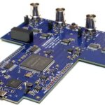
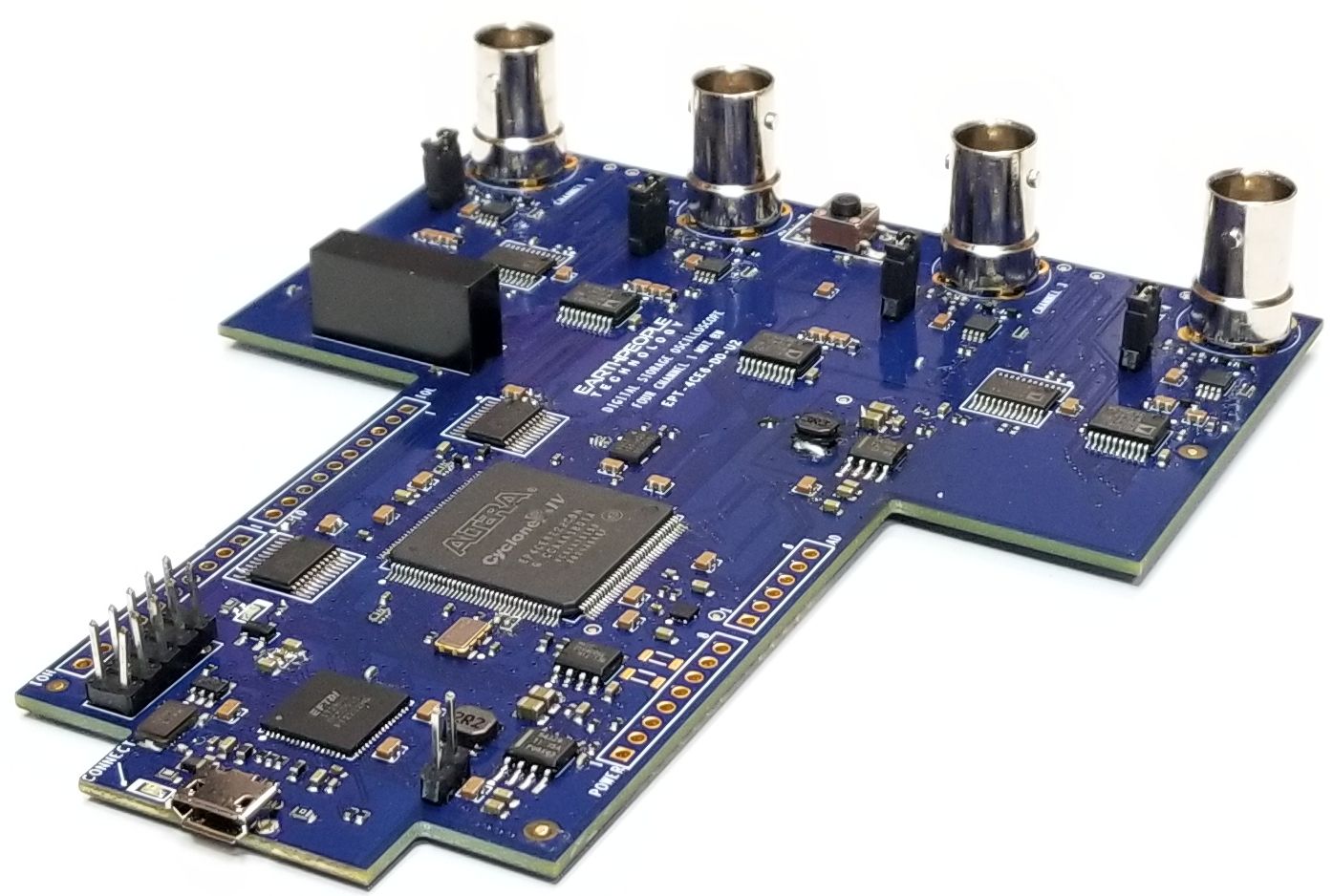
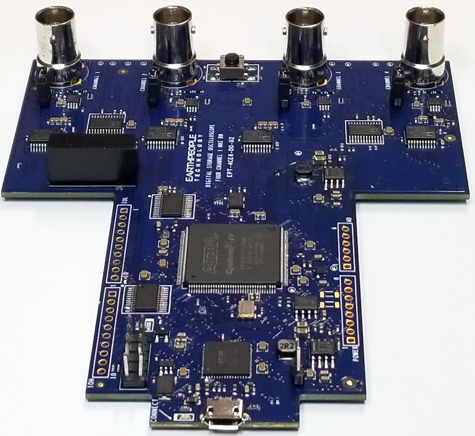
| The Earth People Technology DSO 100M development system is a fully functional USB Digital Storage Oscilloscope. It was designed to be open, flexible and easy to modify. This Open Source Development System allows the user to understand the basics of the typical DSO. All source code along with compiled projects are made available. The user can modify the Verilog code in the FPGA as well as the C# project known as the UnoProlyzer. |
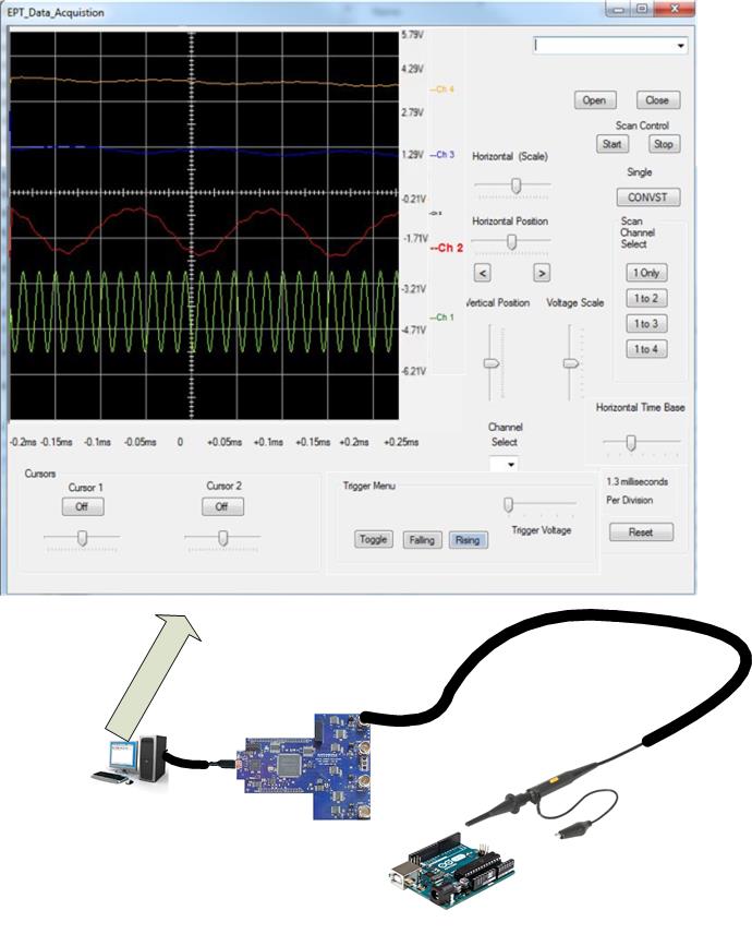
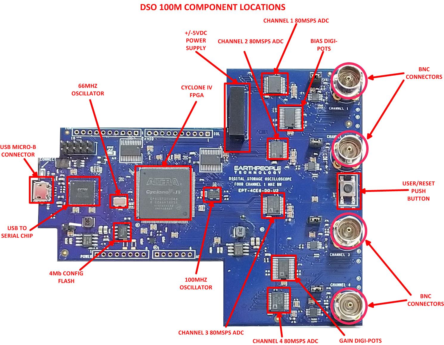
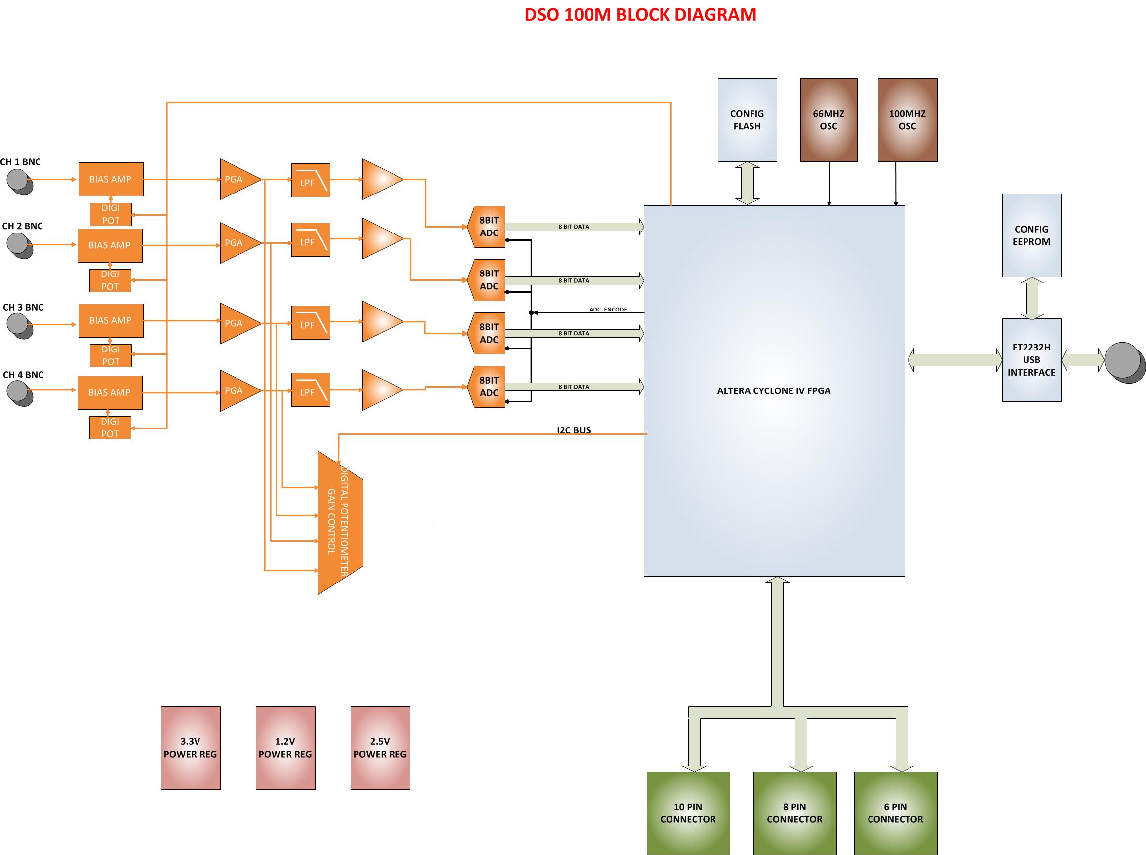
| The DSO 100M includes all the hardware necessary to understand the modern Digital Storage Oscilloscope. Each section of the hardware has been meticulously designed to ensure consistent operation with the PC application. Block Diagram below |
Hardware Features:
|
| The DSO 100M analog front end has been meticulously designed and tested to provide a noise and distortion free analog path to the ADC. To ensure the distortion free signal, a bias amplifier is included using an OPA1602 Op-Amp along with digital selectable gain using a AD5263 Digital Potentiometer. Each BNC connector is 50 Ohm impedance matched on the PCB. A precision +/- 5V DC-DC brick power supply is used to keep the power matched used in powering the Op-Amps and Digital Potentiometers. |
Kit Contents:
|
DVD Contents:
|
Verilog Code Description:
| The FPGA project is written in Verilog code. The code uses EndTerms to allow a flexible communications between the PC application and the FPGA. All communications go through the UC_Controller block. This module interfaces to a memory block and a control register block. When the PC application needs to perform an action, it will write the data to the memory block. Then, it will write an action bit to one of the control registers. The control registers are monitored in the Top Level code to initiate the action. |
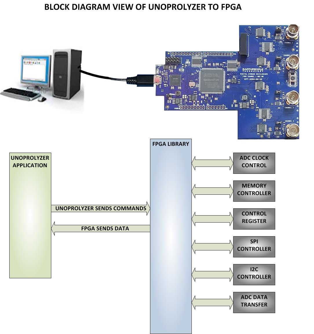
| There are three main components that comprise the communication part of the FPGA code base. There are also several sub-processes that are required for the proper operation of the entire DSO 100M. The communication components: |
- Host Interface Component
- ADC Sample Storage Component
- Data Transmit Component
These components depend on the Active Transfer Library
(and conversely on the Active Host dll) to communicate,
initiate functions, start ADC sampling and transmit data.
All source files, compiled projects, testbenches, test
models are included on the EPT Project DVD. Locate the
Projects_HDL folder on the DVD for the project.
The following components make up the FPGA Code Base:
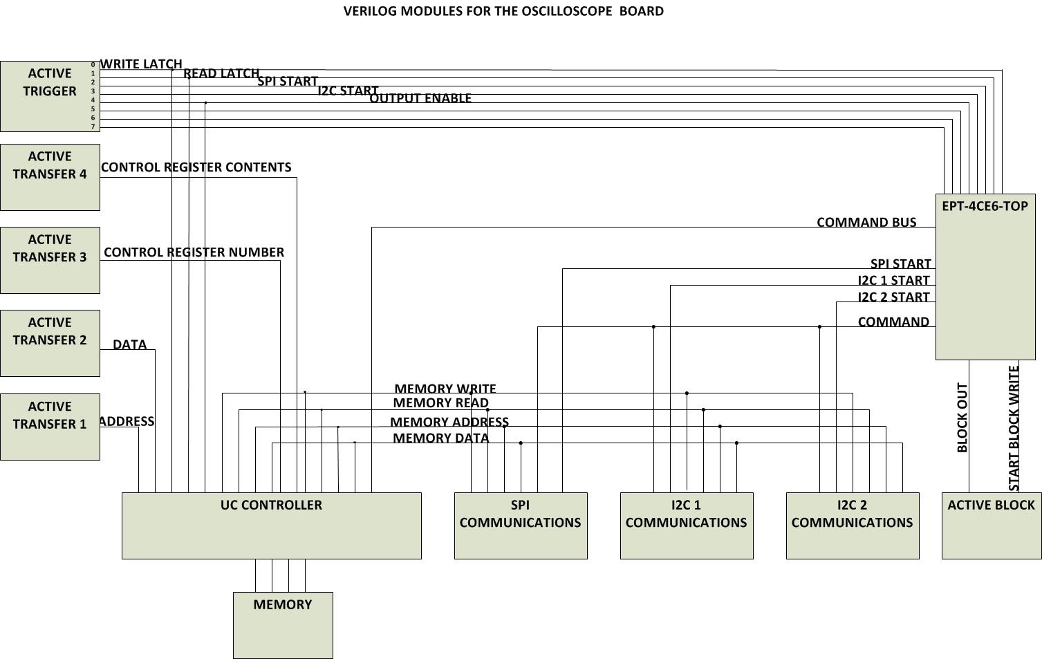
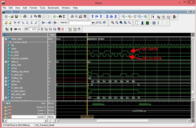
| The entire FPGA project has been simulated and includes and advanced testbench. The user manual includes an extensive description of the Verilog Modules and the interconnection between them. The testbenches and models have been written without any vendor specific IP, so the user can easily set up the free Modelsim from Intel/Altera and get simulating quickly. |
Software Description:
| The DSO 100M utilizes the UnoProLyzer application to control and display the oscilloscope results on a Windows PC. The UnoProLyzer is a C# Windows application. This means it is an event driven application. Any event such as a button press or timer expiring will initiate a function in the application. The application communicates with the FPGA Code via EndTerms. It sets up the buttons, timers and display in the Window. The applications waits in idle for the user to initiate an event, or an automatic event initiation. |
User events are as follows:
- Load the application
- Connect to the DSO 100M board
- Select channels to display
- Start the oscilloscope
- Select channel to process
- Horizontal Zoom on selected channel
- Vertical dynamic range selection
- Horizontal Timebase selection
- Triggering
- Cursor Measurement
Automatic Events are:
- Countdown Timer Expiration
- ADC storage data callback
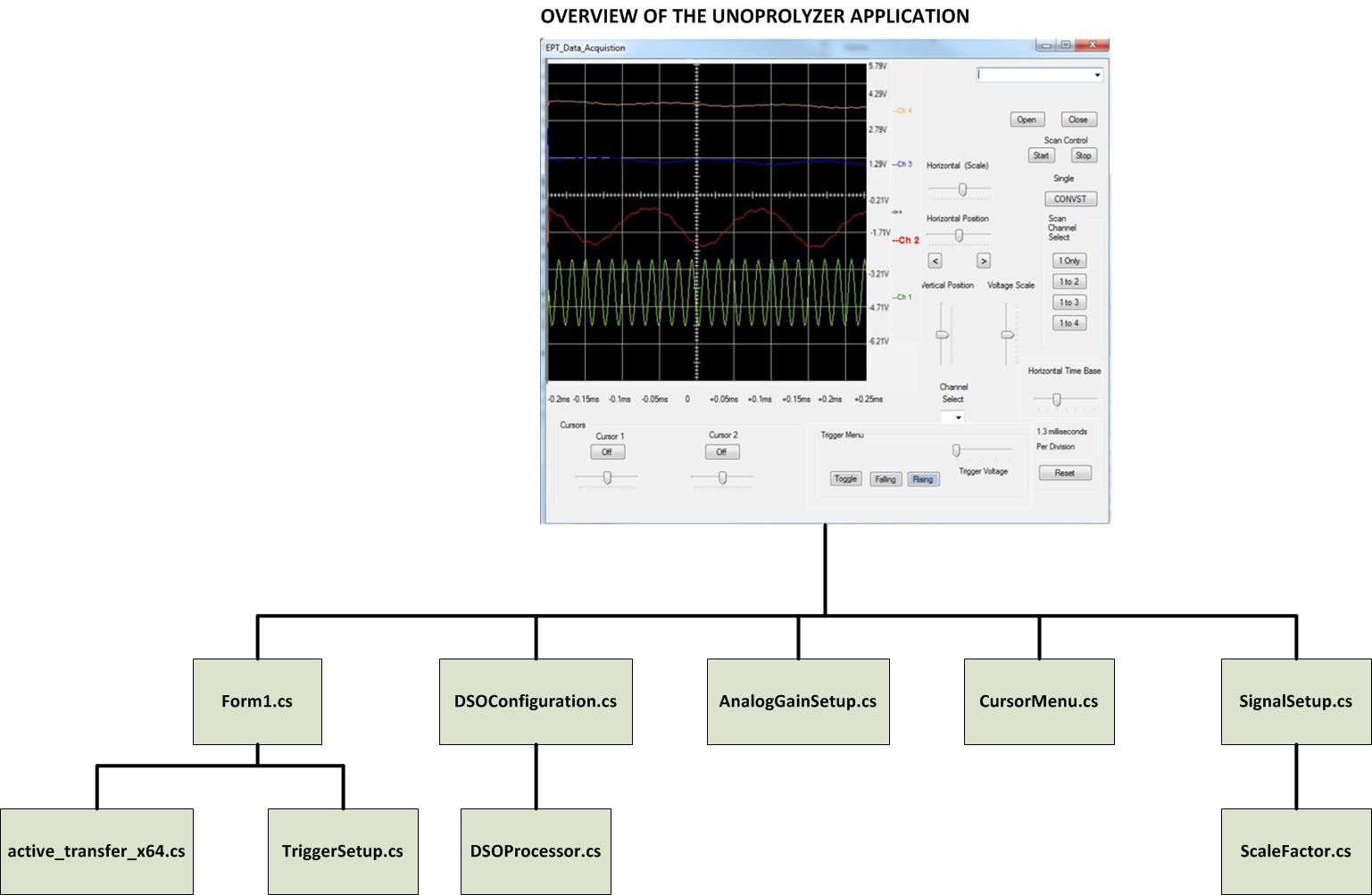
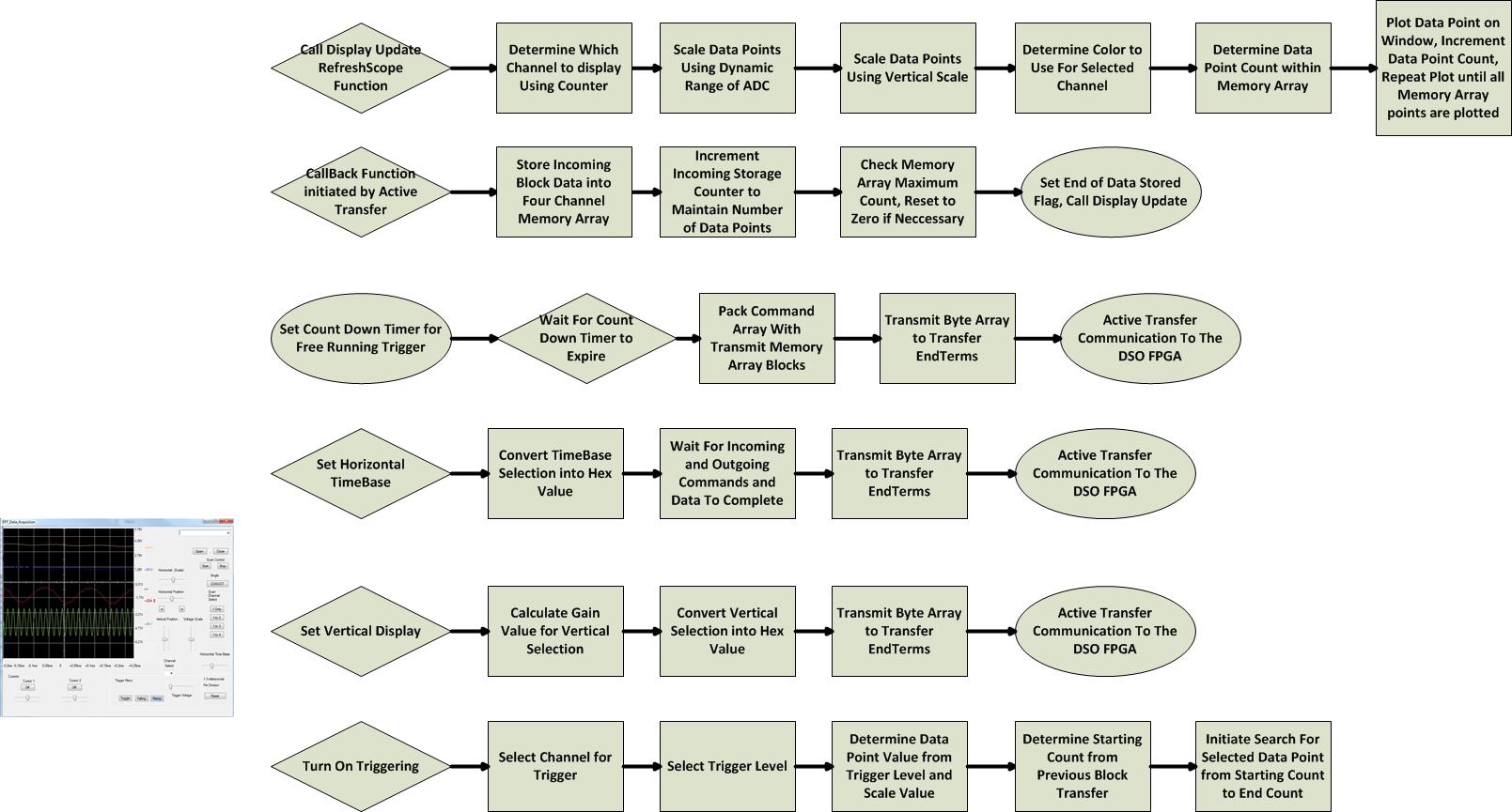
Software Flow Diagram:
| The software flow diagram below shows some of the complexity of the UnoProLyzer. Each path starts off with an event, either user or automatic. The user will select channels to display, set the Horizontal Timebase to use by the ADC’s, set the Vertical Dynamic Range to display of each channel, then start the display of the analog signals acquired by each ADC. |
DSO Programming:
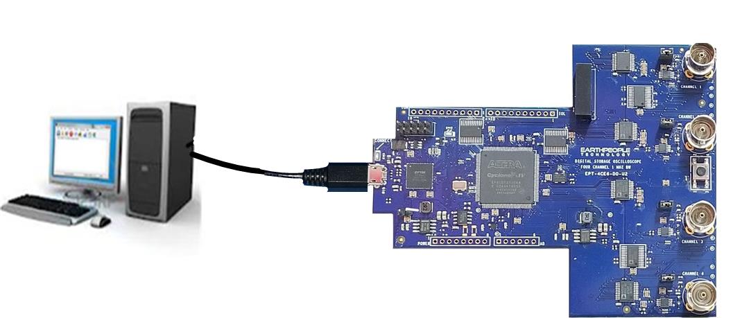
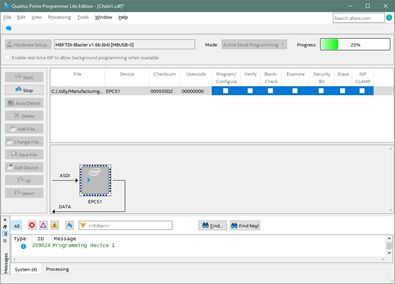
| The DSO is easily programmed from the Quartus Lite Software. Just plug a Micro B USB cable from an open Port on the PC to the Connector on the DSO 100M and load the drivers. A proprietary *.dll from EPT allows the DSO 100M Configuration Flash to be programmed directly from Quartus. |
Downloads
| 85-000100 | DSO 100M Development System User Manual | EPT_DSO_100M_DEV_SYS_UM.pdf |
| 95-000100 | DSO 100M Development System Data Sheet | EPT_DSO_100M_DEV_SYS_DS.pdf |
| 45-000100 | DSO 100M Development System Project DVD | DSO_100M_DEV_SYS_PROJECT_2.8_DVD |
| 55-000100 | DSO 100M Development System Schematics | EPT_4CE6_DO_U2_SCHEMATIC_V4.PDF |
| 35-000001 | EPT Drivers | EPT_2.08.24.ZIP |



Sorry, the comment form is closed at this time.